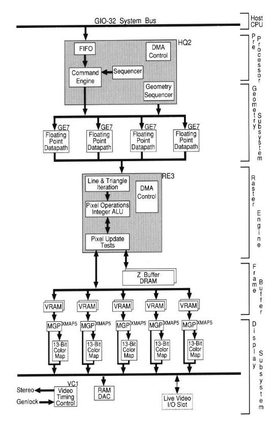
Figure 1 GIO-32 System Bus Block Diagram
Version 1.0
Copyright © 1992 by Silicon Graphics, Inc. All rights reserved.
Silicon Graphics, the Silicon Graphics logo. and IRIS are registered trademarks, and IRIS Indigo, IRIS Indigo Elan, Personal IRIS, IRIS Graphics Library, IRIS GL, Elan Graphics, IRIX, IRIS Showcase, IRIS Explorer, CASEVision, NetVisualyzer, WorkSpace, System Manager, Imagevision, and Virtual24 are trademarks of Silicon Graphics, Inc.
UNIX is a registered trademark of AT&T Bell Laboratories. X-Windows is a trademark of Xerox Corporation. X-Window System is a trademark of the Massachusetts Institute of Technology. All other trademarks and registered trademarks are the properties of their respective holders.
Published in the United States of America. The specifications noted in this document are subject to change without notice.
1. Introduction
2. Technology
3. Software Environment
4. Architecture
5. Features
Elan GraphicsTM is Silicon Graphics'® latest breakthrough in fast, realistic graphics technology for desktop systems. Previous 3D desktop systems were the product of trade-offs between speed, functionality, and size. No longer. Elan Graphics combines the latest advances in VLSI design, graphics architecture, and packaging to bring industry leading graphics to the desktop.
Elan Graphics combines not only outstanding polygon transformation and display performance, but also a feature set unavailable until now in a graphics subsystem priced this affordably. Each of the three new IRIS Indigo platforms, that use the hardware-based Elan Graphics subsystem realize significant 3D performance increases over the entry IRIS Indigo system, which handles graphics processing with the CPU, In addition, Elan Graphics supports 1280 x 1024 screen resolution.
Elan Graphics is available in these desktop configurations:
Elan Graphics includes:
Advanced graphics features include hardware support for:
Elan Graphics provides an unprecedented level of graphics price/performance because of breakthroughs in three critical areas: VLSI design, graphics architecture, and electronics packaging.
The heart of the Elan Graphics subsystem contains 25 custom VLSI chips based on seven new custom VLSI designs. Together, these 25 ASICS total over 700,000 custom gates. Elan Graphics achieves a 15-fold increase in the level of integration over Silicon Graphics' previous graphics architectures.
Among the most significant new VLSI designs are;
Elan Graphics was developed using a hierarchical top-down design approach that allows simulation at the behavioral, functional, and gate levels. In-depth simulation of the overall design throughout the construction allowed the design team to put together this complex system.
The Geometry Engine (GE7) at the heart of Elan Graphics was designed with a general purpose microprogrammed floating point datapath architecture. This allows flexible implementation of a variety of algorithms. Added to the general purpose floating point core are many features that ensure high execution efficiency for graphics-related algorithms. The design team paid special attention to internal busing structures, to data stores for variables and intermediate results, and to the construction of the microprogram word. These features result in outstanding GE7 performance for graphics operations.
Multiprocessing in the Geometry Subsystem helps satisfy the heavy computational demands of graphics rendering. Elan Graphics features four GEs arranged in a unique Single Instruction Multiple Data parallel processing structure for an unprecedented 3D graphics price performance ratio. Every instruction issues separate graphics primitives to each of the Geometry Engines, allowing all four to execute the same instruction in one clock cycle, The custom GE7 design includes several special solutions for the SIMD architectural problem.
The custom Raster Engine uses the maximum available bandwidth of today's video RAMs to achieve exceptional framebuffer fill rates for all fill modes. The Raster Engine achieves these fill rates while implementing advanced fill mode features such as Z buffering, depth-cueing, alpha- blending, raster-ops, dithering, stenciling, clipping region checks, and special effects useful in visual simulation.
For a single RE chip to match the available video RAM bandwidth, the design requires very high clocking rates and multiple pipeline levels. The architecture is based on a variable depth pipeline which swings from 25 pipe stages up to a depth of 40 stages. Each pipe stage involves carefully tuned arithmetic units, and the whole engine is directed by a carefully constructed pipeline control mechanism.
The image Z values are stored in a separate Z buffer memory outside the framebuffer video RAMs that hold color values. In order to achieve the same fill rates for Z-Buffered applications and non Z-Buffered applications, the Z buffer is designed with twice the memory bandwidth of the framebuffer. Both buffers are controlled by the RE3.
The GIO-32 bus provides full-speed burst modes that allow close to maximum use of the bus bandwidth. The CPU main memory has sufficient bandwidth to feed to the GIO-32 bus. The combination of a high bandwidth system bus and high bandwidth main memory is essential to both CPU and graphics performances
To make use of the data bandwidth available from the CPU, the Elan Graphics architecture includes a set of high-speed DMA data funnels. The DMA data funnels provide a direct connection between the CPU main memory and the graphics frame and Z Buffers. These funnels can transfer a 32-bit word to or from the graphics buffers at a rate of one word per Raster Engine clock. These powerful pixel transfer rates are excellent for applications such as image processing, paint applications, and desktop publishing, as well as processing user data from a GIO-32 board slot. DMA data funnels are also implemented within the graphics system to support operations such as bit-BLTing and fast background patterning.
In order to feed the rendering system, the CPU must be able to push graphics commands down the graphics pipe at an accelerated rate. Since most high performance drawing commands boil down to a set of vertices describing one or more graphical primitives, the CPU design supports a special graphics DMA for sending down vertices as the basic drawing primitive. Each vertex may have several pieces of information, such as location, color and normals for lighting. Each piece of information can be delivered to the graphics system through a DNIA transaction, which allows overlap between moving the data and setting up the next vertex. The DMA transaction is initiated by a single load instruction to prime the DMA engine, followed by a store instruction to the address of the vertex in user virtual memory. This triggers the DMA transaction inunediately and allows the user total freedom in placement of graphics data in the address space, All of this occurs transparently to the end-user application, requiring no special coding techniques.
Elan Graphics is largely made up of custom ASICs and readily available commercial memory. Proprietary VLSI design allowed for the removal of most other commercial parts. The result is a compact, low-power, reliable design that achieves high manufacturing. yields.
The system employs the latest techniques in surface mount packaging (SMT) and distributes the large number of gates across the seven custom ASICs. The SMT assembly is the current state-of- the-art in reliable, high-yield manufacturing.
Each board is manufactured to specific tolerances to control the impedance characteristics of the signal traces. This provides an envirorunent where transmission line effects on traces can be controlled, and the integrity of inter-chip signals cans be maintained to a high standard. This is also critical to reliability and high-yield manufacturing.
Elan Graphics is comprised of five daughterboards that plug into a base motherboard. This approach has two advantages. First, it is essential to the compactness of the board design. Second, the partitioning allows very high speed critical bus lengths to be kept very short, making significant contributions to manufacturing yield and reliability.
Elan Graphics offers binary compatibility with the rich set of system and application software that is shipped standard with all IRIS products. End-users are presented with an intuitive and visually pleasing graphical interface to the operating system, which makes desktop file operations and system configurations fast and simple. With the development option, programmers are offered an extensive set of both industry-standard and custom libraries and development tools with which to speedily construct applications of any size and complexity.
In addition to the IRIS Graphics Library, X11R4, and IRIX 4.0, Silicon Graphics' version of UNIX, several other libraries are available. These assist programmers in developing multimedia applications incorporating 2D and 3D graphics, as well as support for video I/O devices.
The Audio Library (AL) provides an interface between applications and audio hardware. Some of the features it provides are:
The ImageVision LibraryTM (IL) object-oriented, extensible toolkit is for creating, processing, and displaying images. The toolkit provides a framework for managing and manipulating images to aid image processing applications developers. Some of the features it provides are:
The Elan Graphics architecture provides an order-of-magnitude leap in graphics processing power over the highest perfoffning workstations currently available in the same price class. The tremendous interactive visual realism enabled by Elan Graphics derives from a unique architecture implemented in 25 custom processors designed by Silicon Graphics.
The RISC-based IRIS Indigo host CPU provides the graphics subsystem with the description of 2D and 3D objects. This takes the form of IRIS Graphics LibraryTM commands bundled with world coordinate data. Described are the object's geometric position with respect to the viewer, together with various light sources, color, surface properties, and surface normal vectors used for complex lighting calculations. The Elan Graphics architecture performs transformations and other graphics operations to calculate specific pixel values for each of the 1.3 million pixels on the 1280 x 1024, high-resolution display. Visual data from the RISC host is processed through five pipelined graphics subsystems before being displayed on the screen. These include:
Elan Graphics is connected to the CPU subsystem via the 32-bit GIO-32 bus and the IRIS Indigo graphics interface channel. Drawing commands, in conjunction with world coordinate geometric data, are passed across the GIO-32 bus and written into the graphics input FIFO. The graphics FIFO buffers differences in computation latencies between the CPU-based application program and the Graphics Engines. The FIFO is implemented as a subblock inside the HQ2 chip.
The Command Engine (CE) monitors the output of the graphics FIFO and passes the stream of commands and data sent down by the application program to the Geometry Subsystem. The CE analyzes the command stream to determine the types of graphical primitives being received and to uncover the boundaries between these primitives. Based on the results of the analysis, the Command Engine delegates primitives to each of the four Geometry Engines. The data is read from the FIFO and passed to the delegated Geometry Engine. The Command Engine fills in any graphical parameters not supplied by the user from the state variables specified by earlier subroutine calls, and outputs a complete packet of parameters to the Geometry Engine. The Command Engine accepts coordinate data from the CPU in four formats:
Color data are also accepted in packed byte format. The Command Engine converts all incoming data words to a uniform floating point format regardless of the input data representation. The Command Engine is implemented as a microprogrammed processor running inside the HQ2 chip.
Figure 1 GIO-32 System Bus Block Diagram
At the heart of the Geometry Subsystem is the GE7 Geometry Engine, a custom floating point data path designed by Silicon Graphics. Four geometry engines execute together as a SIMD machine under the control of a centralized sequencer. The geometry sequencer is implemented in the HQ2 gate array. The sequencer addresses a wide microinstruction memory whose contents are distributed to each of the four GE7s simultaneously. Each Geometry Engine operates on a separate primitive, with the four GE7s operating on four primitives concurrently. The data for each primitive is distributed to the Geometry Engines by the Command Engine. Each GE7 is capable of 32 million floating point operations per second (MFLOPS), making for a peak aggregate rate of 128 MFLOPS.
The GE7 core is structured to be a general-purpose floating-point data path. There is a short computation latency for maximum throughput efficiency. Two separate arithmetic blocks, one multiply and one add, operate in parallel to achieve the 32 MFLOPS rate. This general-purpose datapath is enhanced with special busing structures into and out of the arithmetic blocks. Additionally, the inclusion of several data stores ensures quick operand retrieval and result storage. These enhancements, useful on a GE7 uniprocessor, are coupled with unique flow of control instructions and data manipulation paradigms allowing four GE7s to operate in a SIMD arrangement and achieve maximum use of the arithmetic blocks.
Each Geometry Engine receives a stream of single-precision floating point data words representing vertices in the world coordinate system, together with attributes for each vertex. Transformations are done using 4 x 4 matrix stack to rotate, translate, and scale incoming vertices with respect to the eye of the viewer. The transformations allow 2D and 3D objects to be viewed at any size and from any angle. The result of the transformation is a set of coordinates in a homogeneous coordinate system. A 3 x 3 matrix stack is used to transform surface normals.
The next task is to light vertices to improve the viewing and understanding of surface contours and shapes. The Geometry Engines maintain the position, direction, and intensity specifications for lighting calculations. Up to eight point-source lights or spotlights are supported. Material specifications include ambient, diffuse, and specular reflectance parameters, and lighting model information. The color applied to each vertex is a function of the vertex position, the surface normal direction, the lighting model, the lights, and the characteristics of the surface. The result of the lighting calculation is either a set of eight-bit red, green. blue and alpha values (in RGB mode) or a single 12-bit color index (in color index mode).
Primitives are then clipped to a 6-plane bounding box describing what region of homogenous coordinate space is visible to the viewer. The ability to clip against additional arbitrary planes is available. A fast accept/reject clip-checking algorithm eliminates the need for complex clipping calculations in most cases. When clipping is required, a Cohen-Sutherland clipping algorithm is implemented. The vertices of the clipped primitive data go through a perspective division that provides a perspective view of the resulting object, and compresses the 3D object into a 2D coordinate space for viewing on the screen.
Polygon decomposition in screen coordinate space comes next. All polygons with four or more vertices are broken into multiple independent triangular pieces. The triangles are then handled identically through the remaining graphics pipelines.
The final stage of calculation in the geometry subsystem is to determine a number of parameters pertaining to the triangle or vector. These parameters are used by the raster subsystem to iterate pixels. They include the bottom most pixel center of the triangle, the triangle-edge slopes, and the parameter slopes in both the X and Y directions. Floating-point precision is used to maintain coordinate integrity when calculating slopes. All color and depth components are first coffected to an initial pixel center. As a result, values iterated in the raster subsystem remain planar across polygonal surfaces, and subsequent Z Buffer calculations result in clean intersections. Furthermore, maintaining fractional X and Y position information for all primitives enables correct multi-pass Littering operations.
Each GE7 passes the resulting parameters set to the Raster Subsystem for iteration.
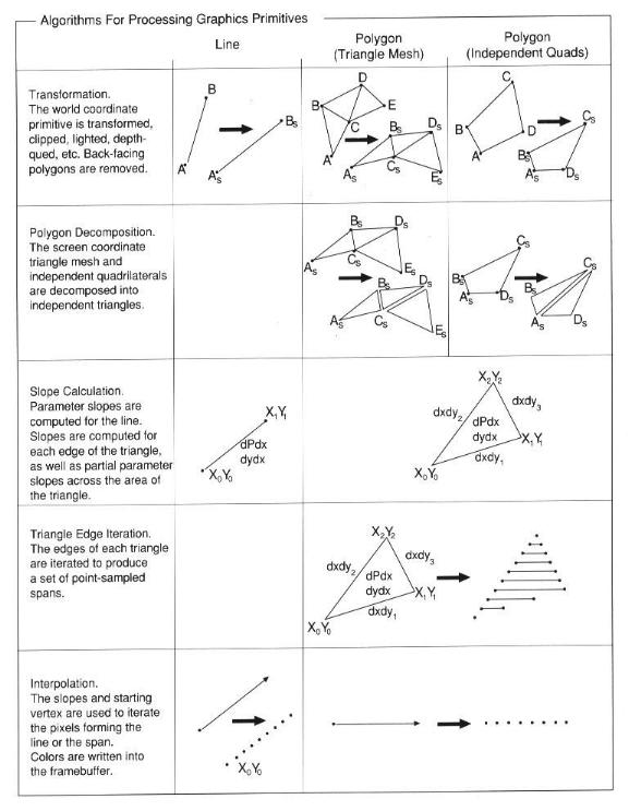
Figure 2 Algorithems For Graphics Primitives
The Raster Subsystem performs the operations required to reduce a vector or triangle description down to the individual pixels to be written into the framebuffer. The core of the raster Subsystem is Silicon Graphics' third-generation Raster Engine, the RE3 chip. The RE3 accepts initial pixel values and parameter slopes from the geometry subsystem and iterates either a vector or a triangle.
The RE3 has a deep and variable length pipeline that swings between 25 and 40 stages depending on the mode of operation. At the front end of the pipeline is a set of DDAs that allow iteration of the various slopes and pixel values initially loaded by the geometry subsystem. The iteration block traverses the line or triangle primitive in full-pixel steps, turning the primitive into an array of pixel values to be sent to the next block.
The pixel operations block has several possible functions. if either pixel blending or raster operations is enabled, this block reads the destination pixel value at the address of the incoming pixel from the iteration block, and performs the appropriate arithmetic or logical merging of the two values. For color index anti-aliased lines. color compare is performed. Fog and haze attenuation is calculated. Pixel values may be dithered before sending to the next block.
The pixel-update-test block determines whether or not a calculated pixel should indeed be written into the framebuffer or Z Buffer. Four simultaneous tests are performed: screen mask check. Clipping ID check, Z compare checks, and stencil value check. The pixel address is tested against two screen masks, each of which provide window clipping for any arrangement of two overlapping rectangular windows. If more complex windowing arrangements are encountered, the clipping ID planes are used to check clipping ID. The operation of the clipping ID planes, the Z Buffer planes, and the stencil planes are described in more detail elsewhere in this report. if all four pixel-update-tests pass, the pixel value is written to the frimebuffer.
The output pixel value from the RE3 is written into a 5-way interleaved framebuffer. which stores a total of 56 bits (including the Z Buffer) for every pixel on a 1280 x 1024 viewing screen. The make-up of these 56 bitplanes is described below.
There are 24 bitplanes for storing the color information for every pixel. In a single-buffered RE3 mode, these planes store a full-color 24-bit image. In a double-buffered RE3 mode, the front and back buffer are each allotted 12-bits. Incoming 24-bit pixel values are dithered into 4-bit red, 4-bit green, 4-bit blue format producing nearly 24-bit resolution in each 12-bit buffer. For color index modes, the 24 bitplanes provide two full 12-bit color index buffers, one for the front buffer and one for the back buffer.
Elan Graphics includes an optional 24-bit signed Z Buffer. The 24-bit Z coordinate associated with each pixel is stored in the Z-Buffer planes. When hidden-surface removal is performed, the Z coordinate of an incoming pixel is compared to the current depth value already stored in the bitplanes. If the incoming Z coordinate is closer to the user's viewpoint, and therefore visible, the color value of the new pixel is used to update the image bitplanes, and the new Z coordinate value is written into the depth planes at the same location. Conversely, if the incoming Z coordinate is farther from the viewer, the new color value is ignored.
When running non-Z-Buffered applications these 24 depth planes may be used as a second full- color 24-bit set of color planes, used identically to the standard color framebuffer,
Note: as stencil planes are added through IRIS Graphics Library control, they are stolen from the low order bits of the Z Buffer, with an effect on Z Buffer resolution.
Elan Graphics supports from 1 to 4 stencil planes. These planes reside in the low-order bits of the Z Buffer. The Raster Engine has the ability to conditionally clear, write, increment, or decrement these planes independent of Z depth value. This capability allows pixels to be tagged as a way of extending the capability of the depth buffer to do a number of prioritizing algorithms.
The framebuffer dedicates four bits per pixel to overlay or underlay operations. These planes are provided for use by a window manager or by applications that use features such as pop-up menus.
Four-bit planes hold data that define the boundaries of the windows on the screen. Each window opened is assigned a 4-bit clipping ID (CID). Every pixel associated with that window not covered by another window has its CID value written into the window clipping planes, For incoming pixels, the stored CID value is compared to the CID value of the incoming pixel. If a match occurs, the incoming pixel is written to the framebuffer; otherwise the framebuffer is left unchanged. The window clipping planes are used in conjunction with the two screen masks to provide a very general window clipping mechanism.
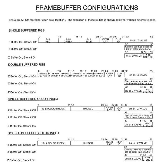
Figure 3 Framebuffer Configurations
The Display Subsystem receives pixel information from the framebuffer, routes it through the appropriate display mode, and sends it to Digital-to-Analog converters for display.
Video timing control, window display mode control, and cursor control are handled by the VC1 gate array. Video timing determines the relationship between active pixels, blanking periods, and sync times. These relationships vary from monitor to monitor. Elan Graphics provides support for the following monitor types:
The VCI stores a window display mode for every pixel on the screen in a run-length encoded table. This display ID (DID) value determines the color mode format used to interpret the data from the image bitplanes. The DID value is passed to the imultimode Graphics Processors that interpret the image bitplanes based on the DID value. Elan Graphics displays multiple images simultaneously, in an overlapping window environment, in single-buffered RGB, double buffered RGB, single-buffered color index, and double-buffered color-index color modes. Simultaneous display of up to 32 unique window styles is allowed.
The VCI controls a cursor memory capable of storing a 32 x 32 three-color cursor glyph. Cursor data is fed into the pixel stream through Multimode Graphics Processors.
Five Multimode Graphics Processors (XMAP5) concurrently receive cursor information from the VC1. The DID values determine how the image data is routed and presented to the Digital-to- Analog Converters. If the overlay/underlay planes are active, they take precedence over the image planes. A 16 x 24 auxiliary lookup table is included for determining overlay/underlay color. The cursor takes the highest precedence and supplants both the image and overlay/underlay planes. The MGPs hold 3 x 24 lookup table for cursor color.
High-speed Digital-to-Analog Converters (DACS) drive the red, green, and blue electron guns of the color display. When the Graphics Subsystem operates in RGB color mode, the DACs receive up to 24 bits of color information for each pixel. Eight of these bits are directly assigned to each of the red, green, and blue DACS to yield more than 16 million colors. The DACs are multiplexed to handle the input from the five parallel pixel pipes. In color-index mode, pixel data packets are used as indices into a 12-bit-in, 24-bit-out color map before being sent to the DACS. This map defines 4096 simultaneously visible colors from a palette of 16.7 million. The pixel-mapping feature of the color-index mode allows screen colors to be quickly modified by simply changing the values stored in the color maps.
The IRIS Elan graphics subsystem uses RAMDAC technology to provide gamma correction under application control. Any 8-bit-to-8-bitmapping can be specified and is applied both to RGB and color index pixels.
The Elan Graphics design provides a port for RGB pixels to be extracted from the Video Bus data stream. This capability allows a Live Video I/O board to be plugged into the Video Bus for real- time capture of the contents of the graphics framebuffer (which can then be sent to the video card), and real-time display of video input on the main graphics monitor.
Genlock is available for both high and low resolution video signals.
IRIS Indigo XS, XS24, and Elan are shipped stereo-ready with a multi-sync high-resolution monitor. To actually utilize the stereoscopic viewing option, users must obtain the StereoView option, including an LED emitter synchronized to the monitor refresh rate of 12OHz and a pair of lightweight LCD shutter glasses. Monitor over 19 inches come Stereo ready.
After being projected to the screen by the Geometry Subsystem, all vertices retain their fractional positioning information instead of being coerced into integers. This gives an accurate description of the primitive's position in a floating-point space. Without this feature, primitives would be rendered incorrectly and would jitter as they move, also causing serious problems with the anti- aliasing features described below.
The pixel data in the framebuffer is replaced with weighted average of itself and the pixel data being drawn. The user selects the function controlling both the source and destination factors used in the blend.
Once common blend operation uses the alpha component of the pixel being drawn as the source factor and one minus alpha as the destination factor. The greater the alpha value, the more weight is given to the incoming data in the blend. This method is used to draw anti-aliased lines and to generate transparencies. It can be used anytime subpixel coverage is demanded.
Blending results are best when drawn into a 24-bit framebuffer, especially when blending in multiple passes. For this reason, it is best to perform the blqiding in single-bufferRGB mode. For those who require smooth motion and are not drawing with Z Buffering enabled, it is possible to blend the pixel data into the Z Buffer and copy each completed frame from the Z Buffer to the framebuffer, Because of the fast pixel copy rates, this method achieves smooth motion.
To render an anti-aliased point, a 2 x 2 grid of pixels is used to approximate the area covered by a filtered point. The four pixels are given blend weights proportional to the distance from their pixel centers to the actual point location in sub-pixel space.
Lines are anti-aliased by drawing a multi-pixel-wide line with higher weights for pixels closer to the line in the minor axis. and lower values toward the outer pixels. Effectively, we are approximating the location of a line by a wide line that is filtered in the minor axis. Similar to points, RGB lines are blended into the framebuffer by the weights. For color indexed anti-aliased lines, instead of generating a weight for blending, the hardware substitutes the lower 4 bits of the color index value. The new color then indexes into a ramp in the color look-up tables.
As the slope of a line gets closer to 45 degrees, pixels that approximate the line should get brighter since fewer pixels span the same length on a Faster screen. To achieve this, the coverage terms are adjusted by the slope of the line. The weights are higher for diagonal lines and lower for horizontal and vertical lines, A hardware lookup table uses the line slope to correctly generate the weights, and later blend them into the framebuffer. For color indexed lines. the slope is also a factor in determining the new color index value.
So far, the weights of pixels that make up anti-aliased lines have been adjusted only in the minor axis. The endpoints of the lines must also be adjusted in the major axis to avoid popping from one pixel to the next. To correct this, the hardware uses the subpixel information in the major axis to adjust the intensity of the endpoint color. This way the apparent endpoint moves gradually from one pixel to the next.
Elan Graphics uses the CPU main memory as an accumulation buffer to combine or accumulate a set of scenes. The IRIS Graphics Library also allows for a weighted blend of the each of the scenes into the accumulated image. The weight of each scene is defined by the user. These weights can be used with other features of the graphics subsystem (i.e., projection matrix) to define User- Programmed Filter Functions.
When using the accumulation buffer in a double-buffered mode, 12-bit RGB images in the graphics framebuffer are accumulated into 32-bit RGB images in CPU main memory, resulting in a certain loss of image quality. Single-buffered applications make use of the full 24-bit color.
As each frame is accumulated into the SharpScene buffer, a more accurately sampled image is produced. The user can choose to render fewer frames to support real-time constraints, or to render many frames to obtain a high-quality image.
Multi-Pass Spatial Anti-Aliasing is done by rendering the same objects for several frames while moving them spatially. By jittering the subpixel offsets (i.e., projection matrix) and accumulating the scenes together, an anti-aliased image is rendered. Furthermore, the user can choose a desired filter function to define the weights for each pass.
By modifying the projection matrix as images are accumulated, viewing the scene from various points across the aperture of a lens, the sense of depth of field is created. Objects that are further from the focal plane of the lens are blurred while closer objects are made sharper.
An image can be quickly filtered using the accumulation buffer. Since the user has control of the weighted accumulation of each image, and the image can be moved about on screen in multiples of pixel coordinates, the accumulation buffer can be used to convolve the image using many filtering techniques.
The accumulation buffer provides a solution for the problem of spatial aliasing, motion-blur, depth of field, and penumbra. Another feature of the accumulation buffer is that all these techniques can be used together in any combination to render a high-quality image.
The Elan Graphics architecture supports a wide range of lighting capabilities to enable the realistic rendering of geometric primitives. Lighting effects are computed on a per-vertex basis (Phong lighting) and are thus supported in the Geometry Engines.
Elan Graphics supports all of the following IRIS Graphics Library lighting capabilities in hardware.
Up to eight light sources may be used simultaneously. The user can specify the color and position of each light source.
The IRIS Graphics Library allows the user to configure a number of surface properties to achieve a high degree of realism. Specifically, the user can define the emissivity of a surface and its ambient, diffuse, or specular reflectivity, as well as its transparency coefficients. A shininess coefficient is provided to specify how reflective an object is. The Command Processor and Geometry Engines were specifically designed so that surface properties can be modified on a per- vertex basis very quickly. This feature is particularly useful for scientific visualization, For example, an aeronautical engineer can change the diffuse reflectance at every vertex to show the stress contour across an airplane wing.
The user can specify different surface properties for the front and back sides of geometric primitives to display objects whose inside and outside colors differ. This obviates the need to specify and render two separate primitives.
Traditionally, hardware-supported lighting models assume that the viewer and light sources are positioned infinitely far from the object being illuminated, Although the positioning of the viewer and/or light sources at a finite distance from the object can enhance the realism of the scene, these models are often avoided because of costly inverse square root operations. The Elan Graphics Geometry Engines include special VLSI support for computing inverse square roots, thus speeding local lighting calculations enormously.
The IRIS Graphics Library simulates those fog and haze effects required for visual simulation applications by blending the object color with a user-specified fog color. The user also enjoys control over the fog density through the IRIS Graphics Library interface.
The entire Indigo product line offers a software implementation of texture mapping that is capable of generating images of the same high quality as those produced on Silicon Graphics' high-end visualization products. Texture mapping has traditionally been used in fields such as visual simulation and computer animation to enhance scene realism. Textures can add vegetation and trees to barren terrain models without adding geometric complexity. Labels can be applied to computer-modeled package designs to get a better appreciation of how products will actually look. Patterns mapped onto geometric surfaces can provide additional motion and spatial cues that surface shading alone can't offer. For example, a sphere rotating about its axis appears static when displayed as a shaded surface; however, by affixing a pattern to the sphere, its motion can be easily detected.
It is essential that errors be minimized during the texture-mapping process, perspective correction of texture coordinates is performed during the scan-conversion process to prevent textures from "swimming" as an object moves in perspective.
Texture aliasing is minimized by filtering the texture for each pixel textured. without filtering, textures on surfaces appear to sparkle as surfaces move. Filtering is accomplished using a mip- mapping technique, Prefiltered representations of a texture are computed at different levels of resolution. For each pixel textured, an interpolated texture value is derived by sampling pixels from the two maps closest to the required texture resolution. Textures can have 8, 16, 24, or 32 bits per pixel.
A variety of texture types and environments are provided to support the diverse applications of textures. Textures can be defined to repeat across a surface or to clamp outside of a texture's unit range. Textures can be in monochrome or color. with alpha or without. Texture alpha can be used to make a polygon's opacity vary at each pixel. For instance, when an RGBA image of a tree is mapped onto a quadrilateral, objects behind the polygon can appear through the polygon wherever the opacity of the tree map is low, thereby creating the illusion of an actual tree.
Textures can be combined with their surfaces in a variety of wavs. A monochrome texture can be used to blend between the surface color and a constant color to create effects such as grass on dirt or realistic asphalt. By adding alpha, a texture can be used to create translucent clouds. Textures can also be used to modulate a surface's color or be applied as a decal onto a surface.
The Elan Graphics architecture can automatically generate texture coordinates. based on user- specified behavior. This feature can be used to texture map contours onto an object without requiring the user to compute or store texture coordinates for the object.
The stencil bitplanes implemented in the Raster Subsystem depth buffer allow a new mechanism for affecting the results of pixel algorithms. In many ways, the stencil can be thought of as an independent, high-priority Z Buffer. The stencil value can be tested during each pixel write, and the result of the test determines both the resulting stencil value, and whether the pixel algorithm will produce any other result.
One application of the stencil is Z-Buffered image copy. With one pass, the stencil planes record the result of depth comparisons between source and destination areas of the framebuffer; with a second pass, the image is copied from source to destination, with only the pixels that passed the depth comparison being updated. As an example, this method can be employed with a library of small 3D images, such as spheres and rods, to quickly construct molecular models in the framebuffer,
A second application is the ability to draw hollow polygons - useful for visualizing the structure of solid models. By drawing the outline of each facet into the stencil, and subsequently performing Z-Buffered drawings of the whole facet while using the stencil as a mask, the true joining edges of an object's surface can be displayed alone, highlighted, or with the background color filled to expose a hidden-line representation.
Most significantly, the stencil mechanism allows Constructive Solid Geometry pixel algorithms to be implemented in a parallelized environment. The flexible testing and updating constructs designed into the Image Engines allows the construction of unions and intersections of primitive shapes, all with the attributes of texture mapping, transparency, and anti-aliasing.
The Geometry Subsystem supports the definition of six planes in 3D space. Geometric primitives can be clipped against these planes in addition to the normal six planes that describe the current viewing volume, providing an ideal mechanism for viewing the cross-section of model components or volumetric data.
Alternatively. the distance between a primitive and any plane can be calculated. This distance can be used as a texture-mapping coordinate, which then can be used to produce a contour map applicable to any 3D model for improved visualization.
Elan Graphics offers a host of features that greatly enhance the pixel read, write, and copy operation. At the core of these features is a 32-bit DMA channel that provides ultra high-speed pixel transfers between the host, the framebuffer, and the Z Buffer. In addition to the standard 32- bit pixel, packed pixels of sizes 16, 8, and 1-bit are supported. During the transfer, 1 -bit pixels can be expanded into one of two 32-bit packed RGBA values defined by the user. Future releases of the IRIS Graphics Library will support 8-bit to 32-bit expansion (pixel look-up) during transfer.
Those interested in large data sets will discover that pan and zoom are supported by the hardware at interactive rates.
For pixel reads or writes, the screen-relative direction of the read or fill (right-to-left or left-to- right, bottom-to-top or top-to-bottom) is user selectable. Copies from the Z Buffer to the framebuffer are oriented from left-to-write and top-to-bottom. If Z-Buffering is not required, the user can draw a 24-bit image into the Z Buffer, then copy it to the framebuffer one frame at a time. By synchronizing the copy to the screen refresh, it is possible to achieve the effect of true 24-bit double-buffering. This is especially useful when doing multiple-pass blending operations.
Elan Graphics supports high-speed rendering of high-quality spheres. Its intelligent frame buffer allows a sphere to be rendered as a "2 1/2 D" image, i.e. a two-dimensional array of pixel data with a depth value associated with each pixel. These images are rendered using the standard z- buffer algorithm.
Sphere rendering will not be incorporated in to the IRIS Graphics Library at this time. Instead, sample code will be provided for 2 1/2 D and several types of polygonal spheres.