Systems
Power Series
Introduction
General
PowerSeries 4D/420VGX in PowerSeries 4D/240GTX skins.
This series is part of the family of IRIS 4D systems, they were successors to the Professional Iris systems and higher end brothers during the Personal Iris era.
The PowerSeries systems are the first multiprocessor computers made by SiliconGraphics.and were typically shipped in a single or twin tower case, it is the first series of SMP computers made by Silicon Graphics.
PowerSeries systems were first produced in twin tower shaped chassis, later on single tower chassis were introduced. The highend systems (more than 4 CPUs) were shipped in a "refrigerator-style" rack because of space limitations in the deskside cases.
Models
The following list gives a brief introduction into the various models:
| Model | CPU board | CPU | Number | Chassis |
|---|---|---|---|---|
| 4D/120 | IP5 | MIPS R2000 16.7 MHz | 2 | Deskside |
| 4D/210 | IP9 | MIPS R3000 25 MHz | 1 | Deskside |
| 4D/2x0 | IP7 | MIPS R3000 25 MHz | 1, 2, 4 or 8 | Deskside or Rackmount |
| 4D/3x0 | IP7 | MIPS R3000 33 MHz | 1, 2, 4 or 8 | Deskside or Rackmount |
| 4D/4x0 | IP15 | MIPS R3000 40 MHz | 1, 2, 4 or 8 | Deskside or Rackmount |
The individual Models include the number of CPUs installed as the second digit. For example a 4 CPU 33 MHz system is called 4D/340.
In SGI documents the performance for various configurations of Power Series systems is listed as follows:
          4D/120     4D/220     4D/240     4D/280     4D/320     4D/340     4D/380     4D/480
-----------------------------------------------------------------------------------------------
MIPS        20         40         80         --        ~57       ~115        ~230        --
MFLOPS       2          8         16         --        ~10        ~20         ~30        45
Architecture
Although versions with only one CPU do exist, the PowerSeries systems are symmetric multiprocessing machines at their core. The basic POWERpath system design and the main parts of the PowerSeries architecture is shown in the following graph.
  Sync                 Processor                            MPLink
  Bus                     Bus                                 Bus
   |                                                           |
   |--------[CPU/FPU]-------------[1st/2nd level cache]--------|
   |                                                           |
   |--------[CPU/FPU]-------------[1st/2nd level cache]--------|
  ...                                                         ...
   |--------[CPU/FPU]-------------[1st/2nd level cache]--------|
   |                                                           |
   |------------------------------------[System Memory]--------|
   |                                                           |
   |-------------------------------[Graphics Subsystem]--------|
   |                                                           |
   |                                    [VME Interface]--------|
The Processor Bus is a local bus that includes both an 100MB/s data and 100MB/s address bus which connects each processor with it's associated cache. The Sync Bus synchronizes the processors of the system and thus helps in parallel processing of data/programs. MPLink is an asynchronous bus that connects the CPUs and Memory as well as the other Subsystems of the PowerSeries computer.
History
- 1988, October
- first PowerSeries bus-based multiprocessor workstations produced
- 1990
- VGX graphics option introduced
- 1990
- 4D/2x0 systems have been dropped
- 1991, 1st half (June?)
- 4D/4x0 series introduced with 4D/480 (286 MIPS and 70 Mflops) as highend system
Processor
Overview
| Model | CPU Board | Processor | Number | Clockspeed | Cache (d/i) | Cache (2nd) | Floating Point |
|---|---|---|---|---|---|---|---|
| 4D/120 | IP5 | R2000 | 2 | 16.7 MHz | 64KB / 64KB | none | R2010 onboard |
| 4D/210 | IP9 | R3000 | 1 | 25 MHz | 64KB / 64KB | none | R3010 onboard |
| 4D/2x0 | IP7 | R3000 | 2 | 25 MHz | 64KB / 64KB | none | R3010 onboard |
| 4D/310 | IP7 | R3000 | 1 | 33 MHz | 64KB / 64KB | none | R3010 onboard |
| 4D/3x0 | IP7 | R3000 | 2 | 33 MHz | 64KB / 64KB | none | R3010 onboard |
| 4D/4x0 | IP15 | R3000 | 2 | 40 MHz | 64KB / 64KB | none | R3010 onboard |
Installation
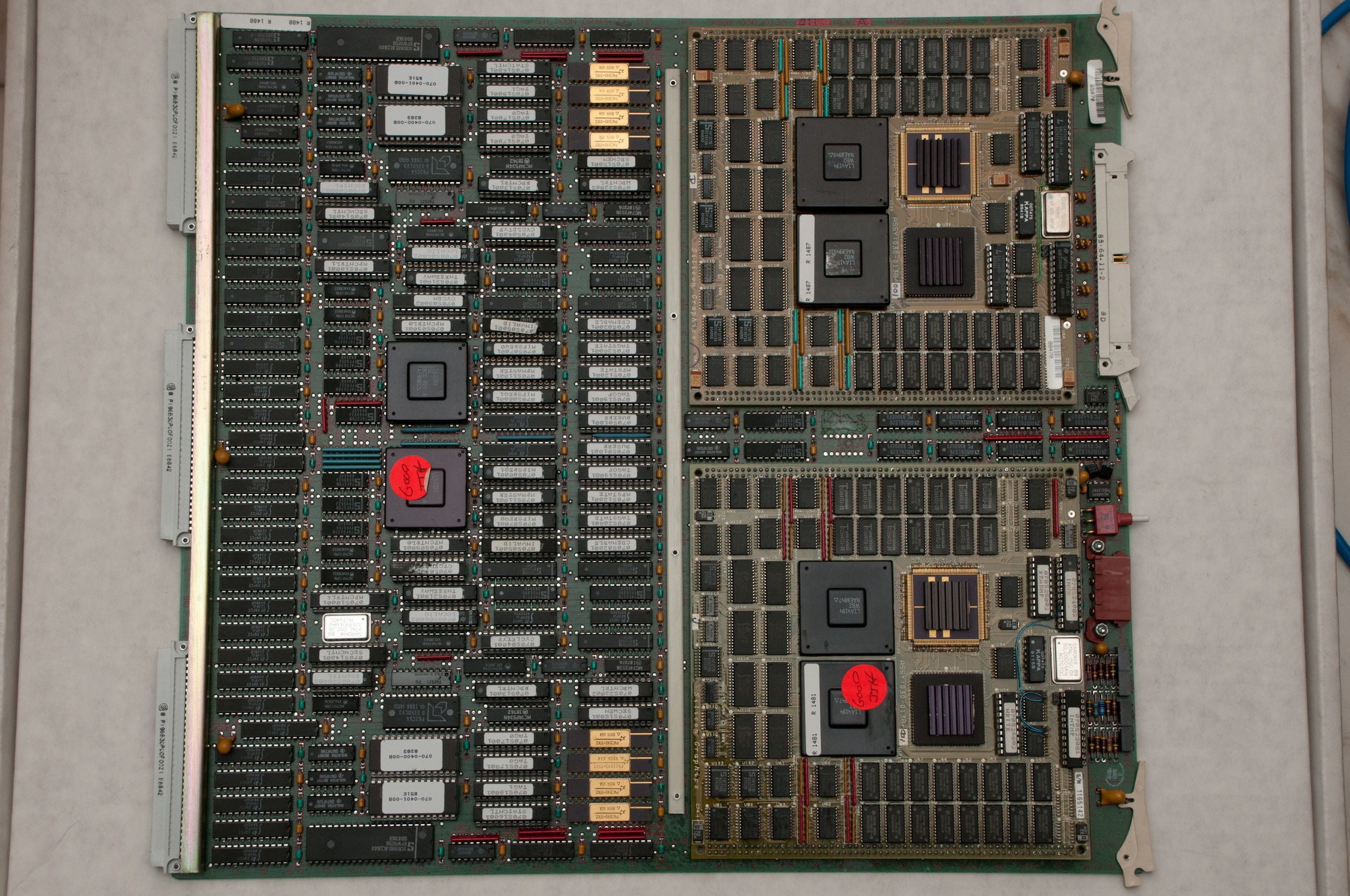
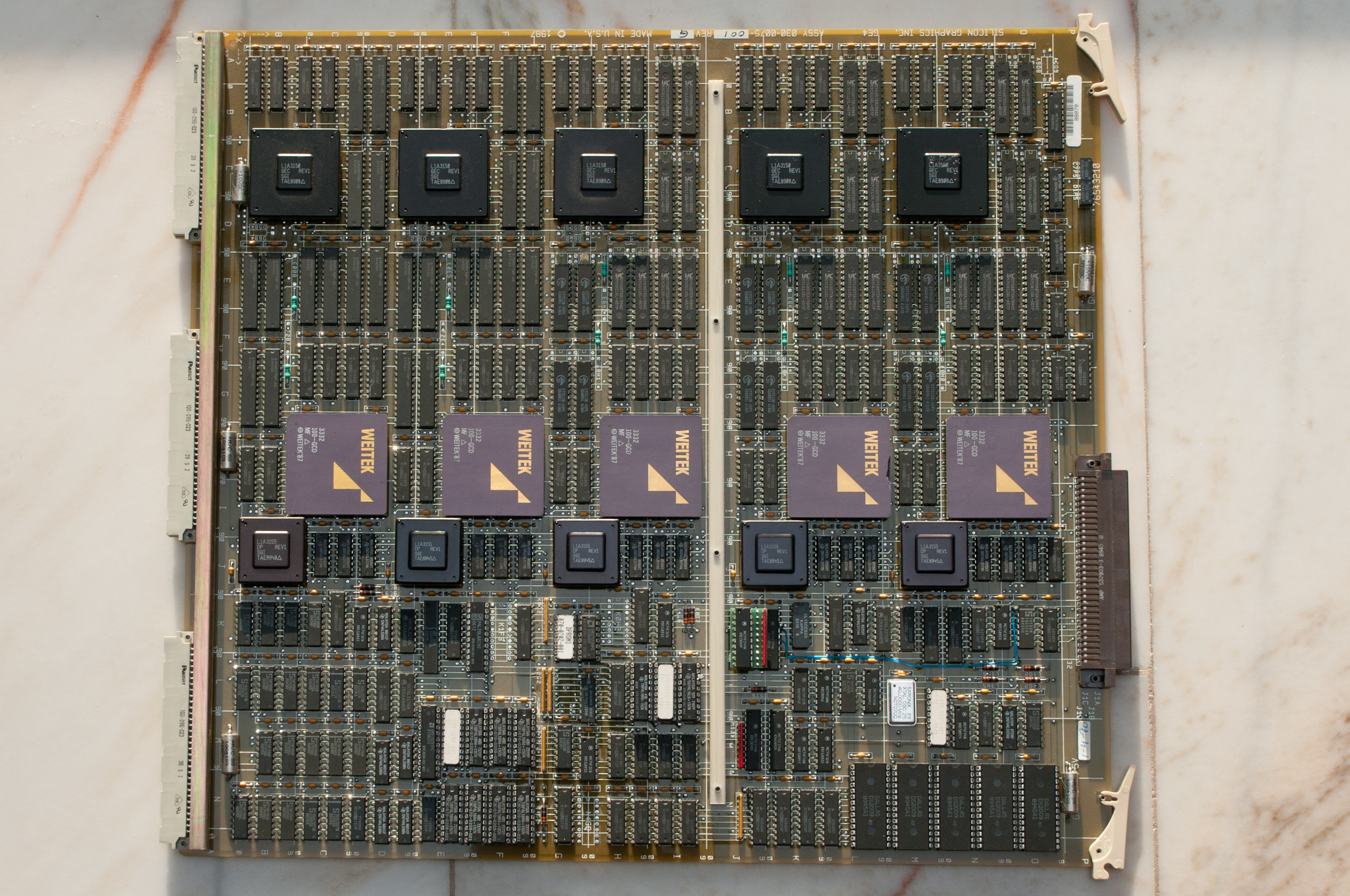
IP7 CPU board, 2 MIPS R3000.
Systems are allowed to have 1 singleprocessor CPU board or up to 2/4 (deskside/rack) dualprocessor CPU boards. So valid numbers of CPUs are 1, 2, 4, 6 and 8. Mixing singleprocessor CPU boards with dualprocessor boards is not supported, but still may work.
The processor boards installed should be of the same type (e.g. all 25MHz IP7) but this is not a requirement. It is known that mixed setups can boot and operate just fine. Implications on CPU performance have not been tested yet but the basic operation is confirmed. The recommended setup is to have the faster CPU board goes into the first slot so that IRIX itself boots on the fastest CPU in the machine.
Status LED
Every CPU board has a full set of LEDs for each CPU installed on the board. With the exception of the primary CPU (CPU #0 on the first CPU board) all CPUs behave the same (this assumes an idling system):
- During POST the CPU LEDs cycle.
- If POST has completed without error only the second LED from the bottom is lit (primary CPU).
- If POST has completed without errors all LEDs blink (other CPUs).
Memory
General
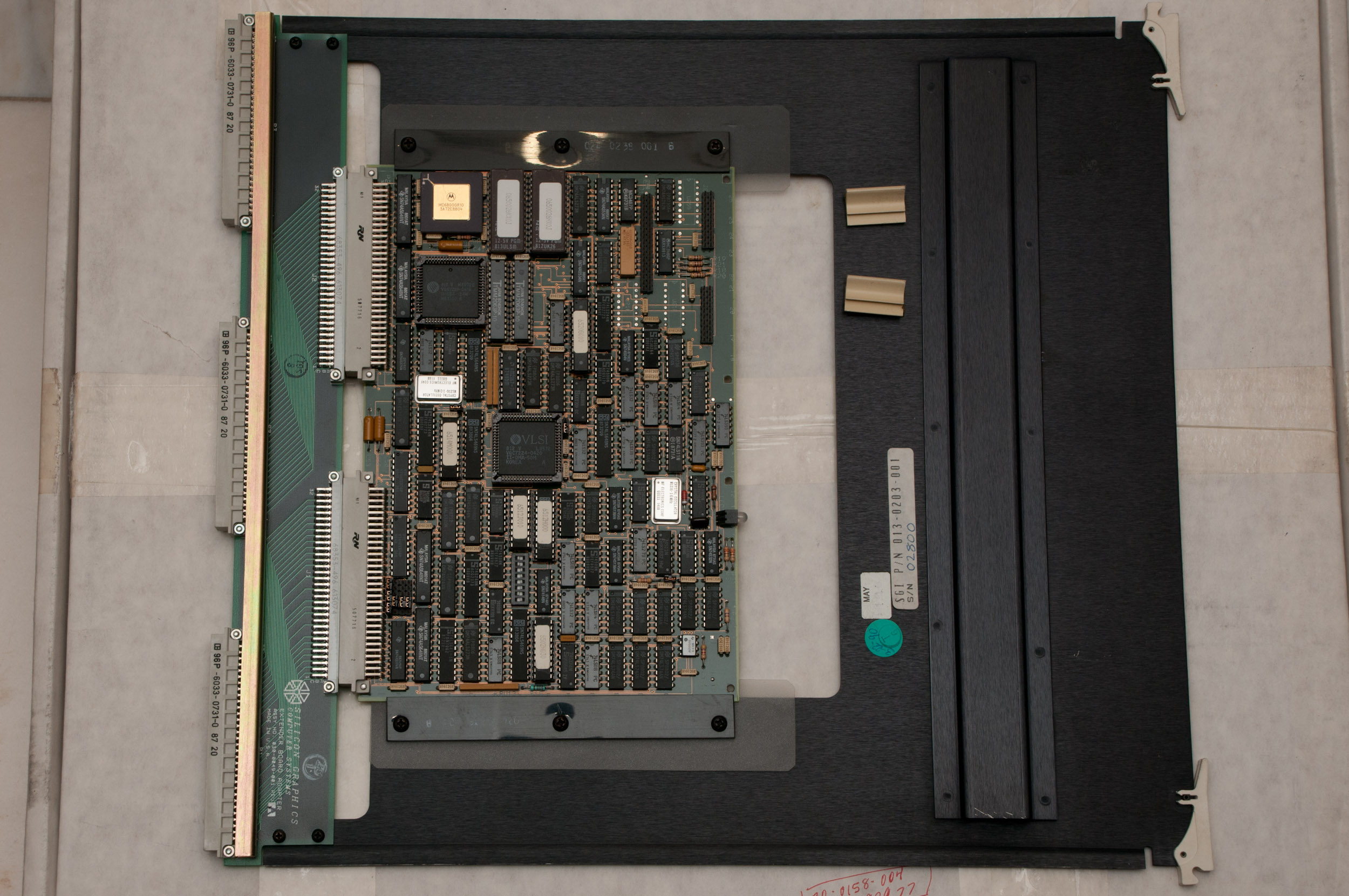
The only CPU board that supports on board memory is the IP9 board from the 4D/210 system. It is only used when no memory expansion card is installed or all banks on the card are filled.
IP9 board
Type:                   proprietary 80pin SIMMs
Sockets:                16 (2 * 8 SIMM sockets)

Minimum configuration:  16 MB (8 * 2MB SIMMs)
Maximum configuration:  32 MB (16 * 2MB SIMMs)
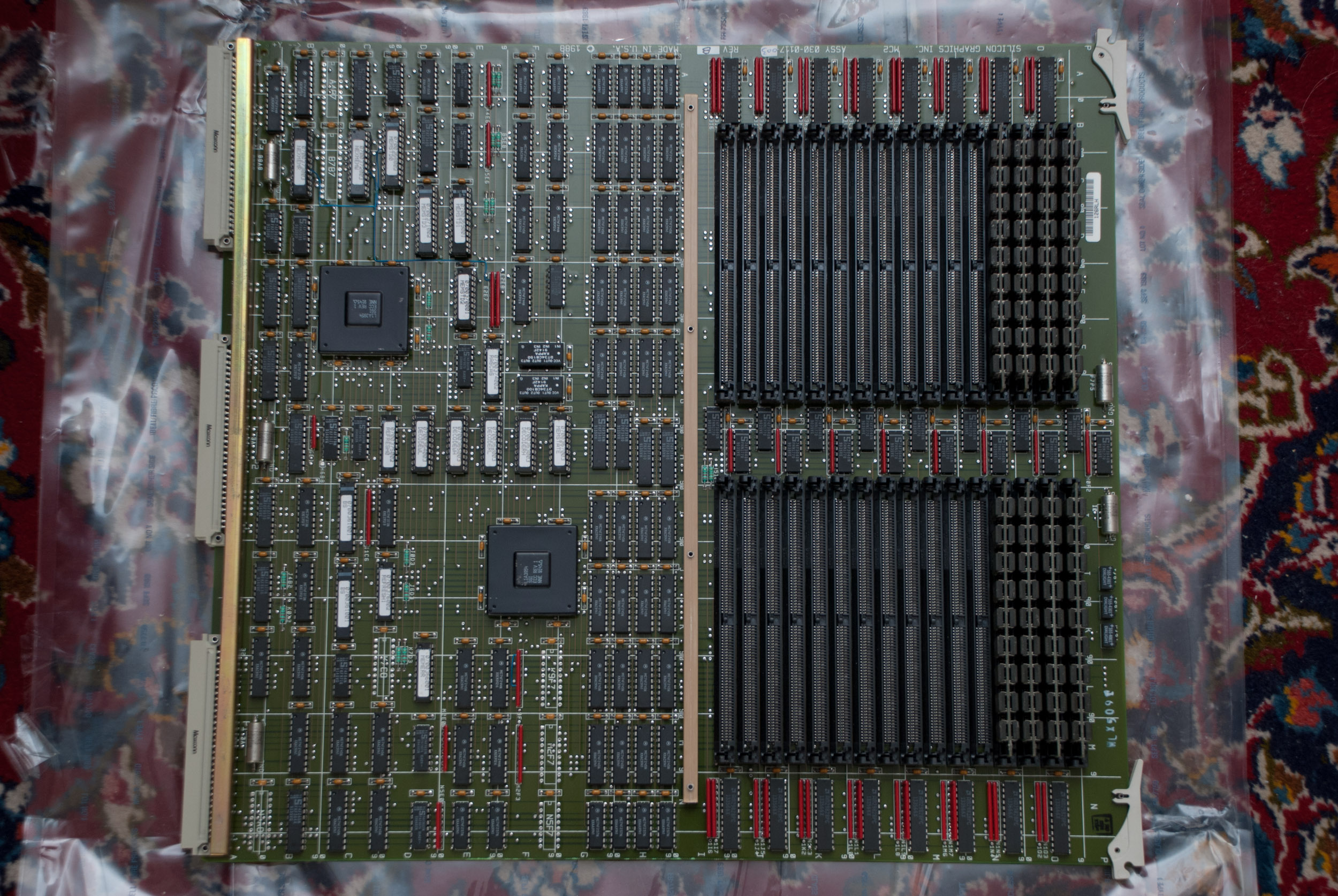
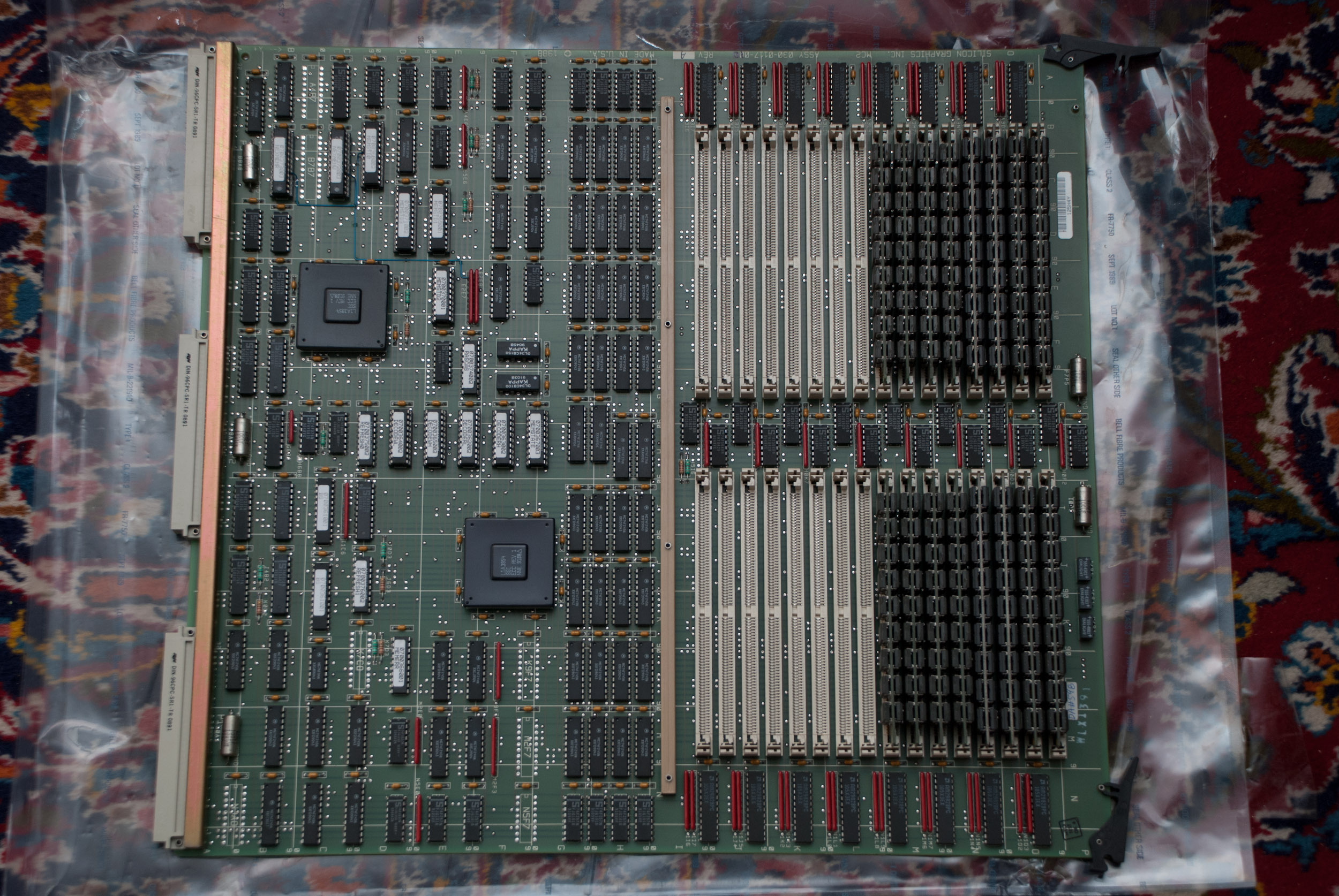
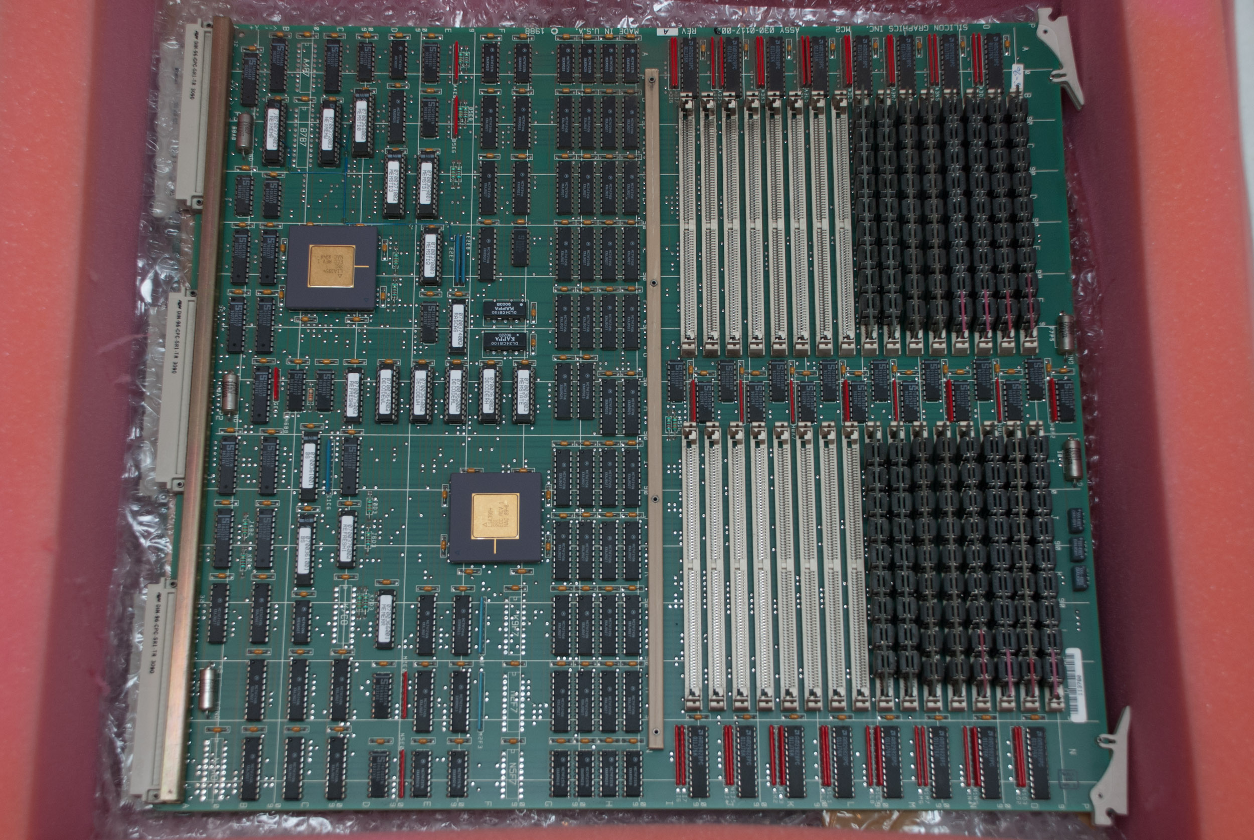
MC2 board
Type:                   proprietary 80pin SIMMs
Sockets:                32 (4 * 8 SIMM sockets)

Minimum configuration:  16 MB (8 * 2MB SIMMs)
Maximum configuration:  256 MB (32 * 8MB SIMMs)
Notes
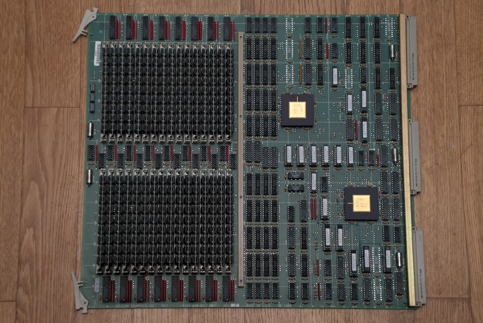
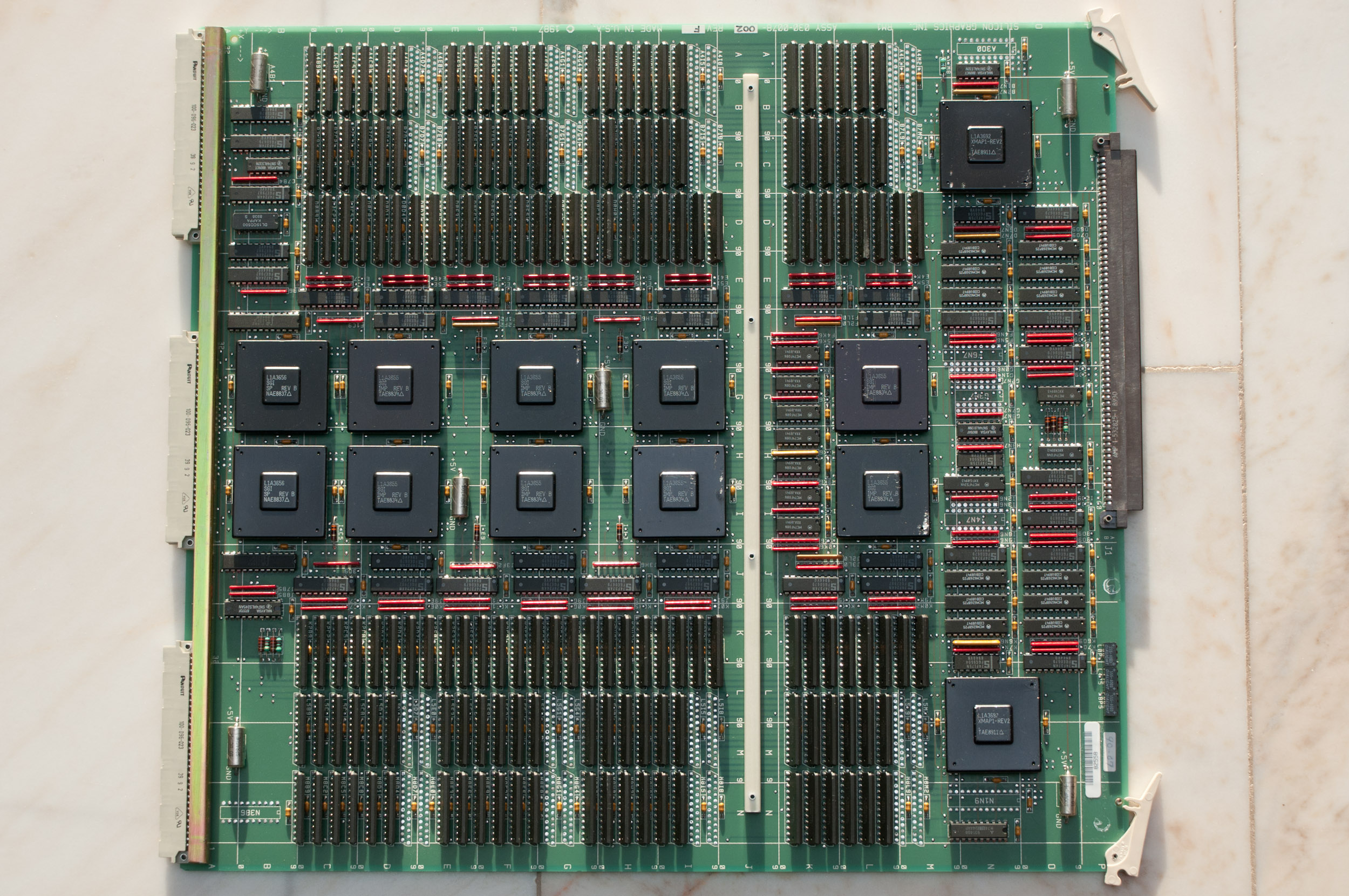
MC2 memory board fully populated.
- Memory in the system may not exceed 256 MB, the maximum of a single MC2 board - although physically 512 MB would fit into a Twin Tower (2 MC2 boards).
- The high density 8MB SIMMs do not work on old revisions of the MC2 memory board. Currently especially 030-0117-001 boards are known to be incompatible with these high density SIMMs.
- Officially an MC2 board may contain only one type of SIMMs (either 2MB or 8MB). It is being reported that some MC2 boards work in a mixed setup. Also, on Twin Towers in it is allowed to have 2 MC2 with different SIMMs in one machine (Twin Tower for example).
- Just to correct the information posted earlier in the This Old SGI FAQ: MC3 memory boards are for Challenge / Onyx systems and not for PowerSeries machines.
Status LED
MC2 boards have two sets of status LEDs. The bottom 4 LEDs are red and sould be off once the system has passed the POST. The 8 green LEDs indicate which SIMM groups are fully populated and accessible.
Graphics
Options
PowerSeries systems were available with a wide range of graphics hardware:
- Server (no Graphics)
- GTX/GTXB Graphics
- VGX/VGXT Graphics
- Reality Engine Graphics
Other
General
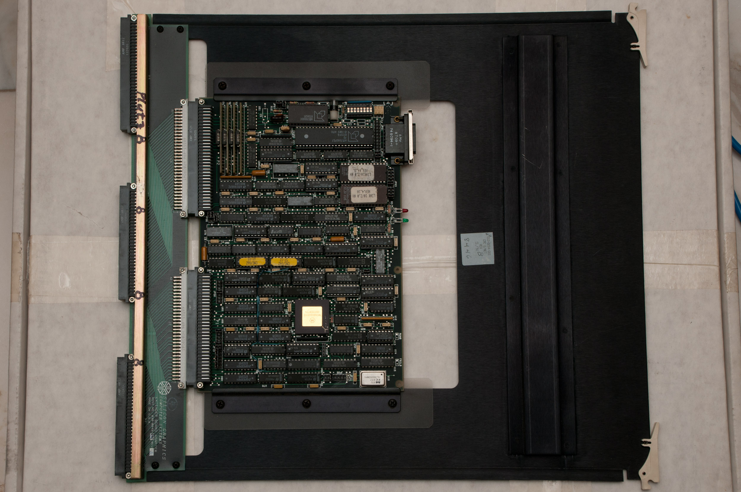
As indicated before the basic IO subsystem is located on it's own board which again is of 9U VME size. Like on the other boards a proprietary bus is used, but this time there is also a proprietary connector that uses the whole card edge which is plugged into the backplane.
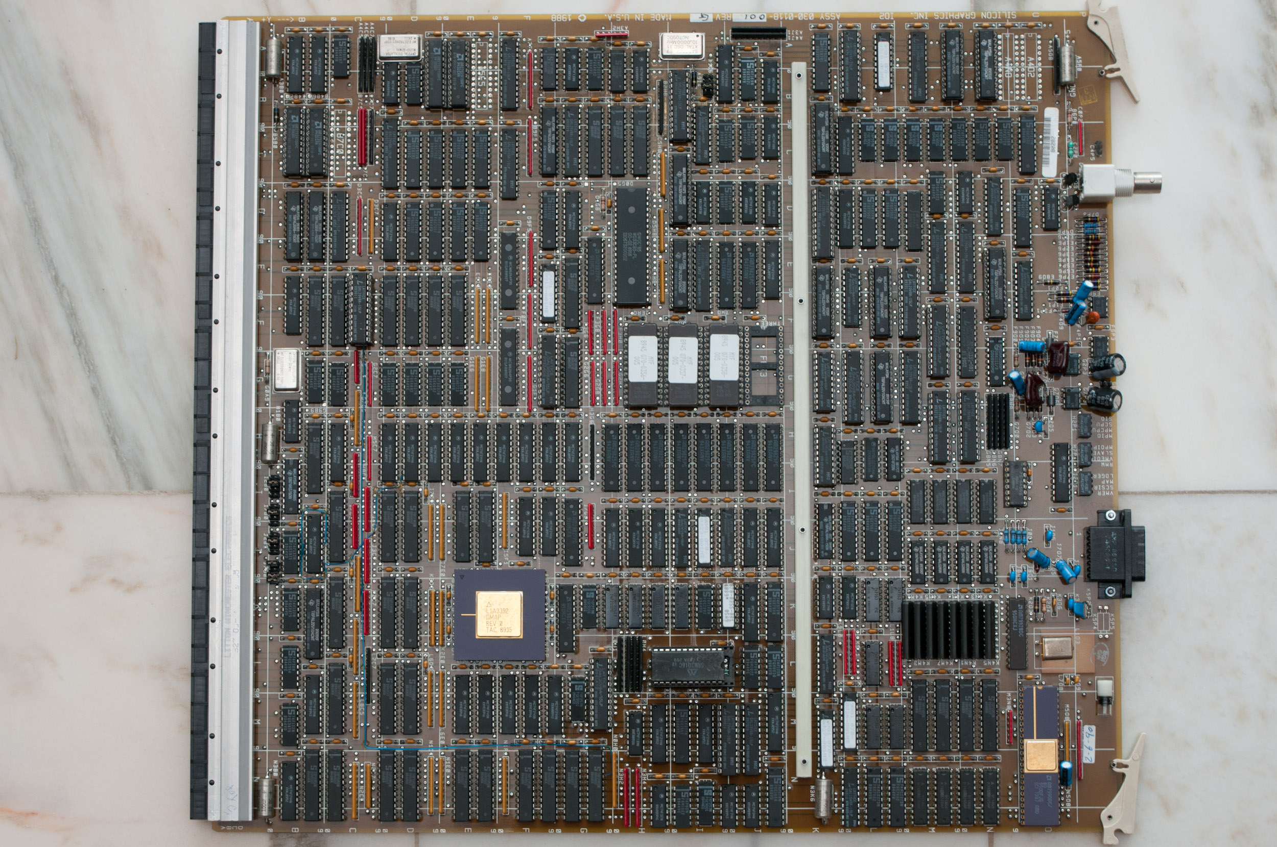
IO2 board

IO2 board.
Original PowerSeries IO board. Provides one SCSI channel which is used via the backplane for internal drives and one Ethernet interface that is connected to the systems IO panel. The SCSI chipset is a Western Digital 33C93.
IO3 board

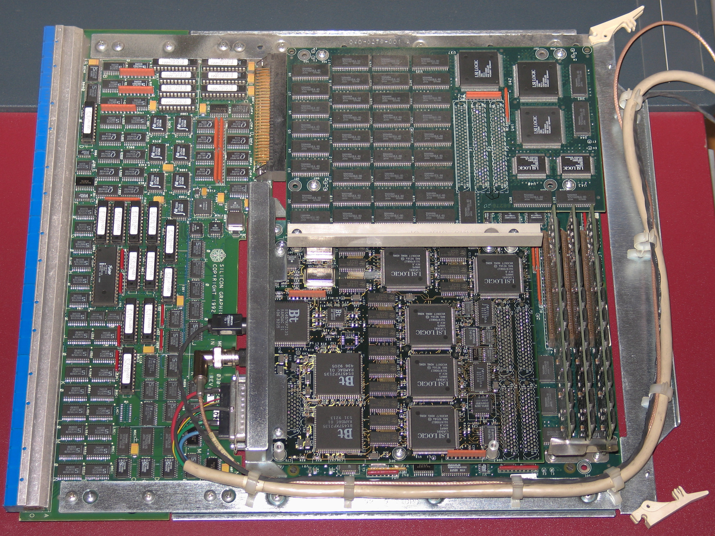
IO3 board.
Next revision of the IO board. Provides also at least one SCSI channel and one Ethernet interface. There may have been versions of this board that did include a second SCSI interface. The SCSI chipset is a Western Digital 33C93A.
IO3B board
The last revision of the PowerSeries IO board. All IO3B boards include one SCSI channel for internal use, a second that can be used via the IO panel and one Ethernet interface also for use via the IO panel. The SCSI chipsets used are Western Digital 33C93A.
This board can be used with PowerSeries (IP5, IP7, IP9, IP15) as well as Crimson (IP17) CPU boards. For PowerSeries support the jumper at position C0F0 needs to be placed on the middle pins.
Connectors
All PowerSeries systems have at least:
- Drives:
- 2 centronics style SCSI connectors below the drivebay
- other SCSI connectors depending on cable/board configuration
- Networking:
- 1 ethernet interface
- Input/Output:
- Keyboard/Mouse
- 4 RS232 serial ports
- 3 Powered Peripheral Ports (8 Pin DIN)
- Graphics:
- 13W3, BNC or VGA depending on hardware installed
The actual connectors present on a PowerSeries system depend very much on the configuration of that system. With additional VME expansions (see below) a lot more/different I/O possibilities are available.
Options
Expansion Slots
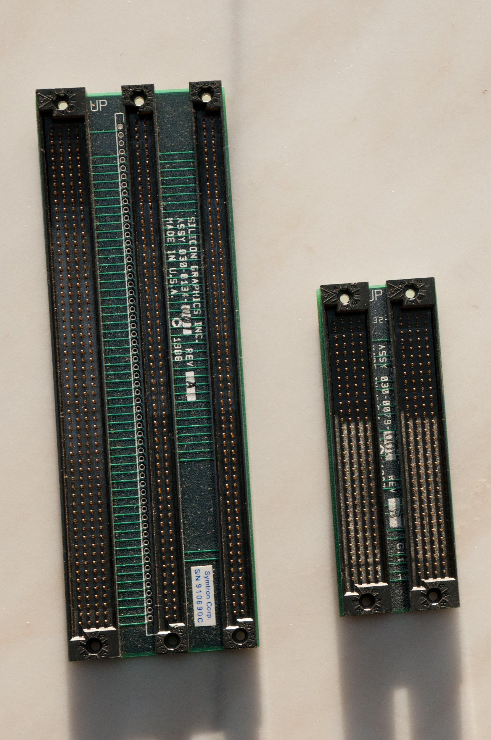
All IO boards contain a VME bus interface that connects to the VME slots of the backplane which can be used to add VME options to PowerSeries systems. The Extender Board Adapter is used to interface 6U VME devices to the 9U VME slots of the backplane.
General rules regarding VME setup:
- populate slots from slot #1 to slot #4
- remove BG/IACK jumper for every slot that cards are installed in
- if one slot is empty the BG/IACK jumpers must be set
The exception to this rule is the Genlock board which always goes in slot #4. If that is installed the genlock jumpers located to left of bottom connector of slot #4 must be in place.
Communications and IO Options
CNC Ethernet
- Network interfaces (4 ethernet or token ring)
- HPPI interface
- FDDI interfaces (up to 4)
Drive Options
- Tape drives: 1/4" (QIC-150), 8mm Exabyte, DAT
- CD-ROM
- Internal disk drives with 1 or 2 GB (approx.)
- External disk drives
Video Options

Video Creator external version.
- Broadcast Video Options
- CG2 / CG3
A graphics output option for G, TG, 8-bit and 12-bit graphics on the Personal Iris, as well as GT and GTX graphics on the PowerSeries. The output format is RGB and can be genlocked to an external video source. - Live Video Digitizer
- Video Creator
- Video Framer
- Video Lab
- Video Splitter
- Multi Channel Option
The Multi-Channel Option is similar to the VideoSplitter except that it has up to six channels and it supports the Reality Engine graphics only. It also supports various timing modes including NTSC and PAL.
Misc Options
- ESDI controller
- SCSI channels (narrow and HVD)
- 6-port serial card
Chassis
Twin Tower
Description
The 15 Slot Twin Tower was used for the early systems with 2 CPU boards: 4D/120, 4D/210, 4D/220, 4D/240 The big "half" houses the boards of the system and has all the external connectors on its back, the small "half" is the drive tower for the internal drives.
width:     65 cm / 26"
height:    66 cm / 26"
depth:     69 cm / 27"

weight:    86 kg / 190 lbs
All systems have the word "PowerSeries" printed on the front. The type of the graphics option installed (at the time the system was shipped) is indicated by the color of top of the two towers. GTX(B) machines have red VGX(T) systems blue and server systems beige top hats.
Backplane Layout
| 1 | VME | The VME Slots have to be filled from left (#1) to right (#4) with no empty slots in-between. |
| 2 | VME | |
| 3 | VME | |
| 4 | VME | |
| 5 | IO | IO Controller |
| 6 | CPU | The slots for CPU boards must be filled from left (#6) to right (#7), so in systems with a single CPU board (single or dual CPU systems) slot #7 remains empty. |
| 7 | CPU | |
| 8 | MEM | Two memory slots. Again the slots have to be filled from left (#8) to right (#9). |
| 9 | MEM | |
| 10 | GFX | How the graphics slots are used depends on the type of graphics option. See Graphics section. |
| 11 | GFX | |
| 12 | GFX | |
| 13 | GFX | |
| 14 | GFX | |
| 15 | GFX |
Status LED
The Twin Tower has a 1 digit LED display located near the power switch on the drive tower. In case of an error it shows "F". As long as the system is in the PROM it cycles between "1" and "2". If the system is running it cycles between "0" and "1".
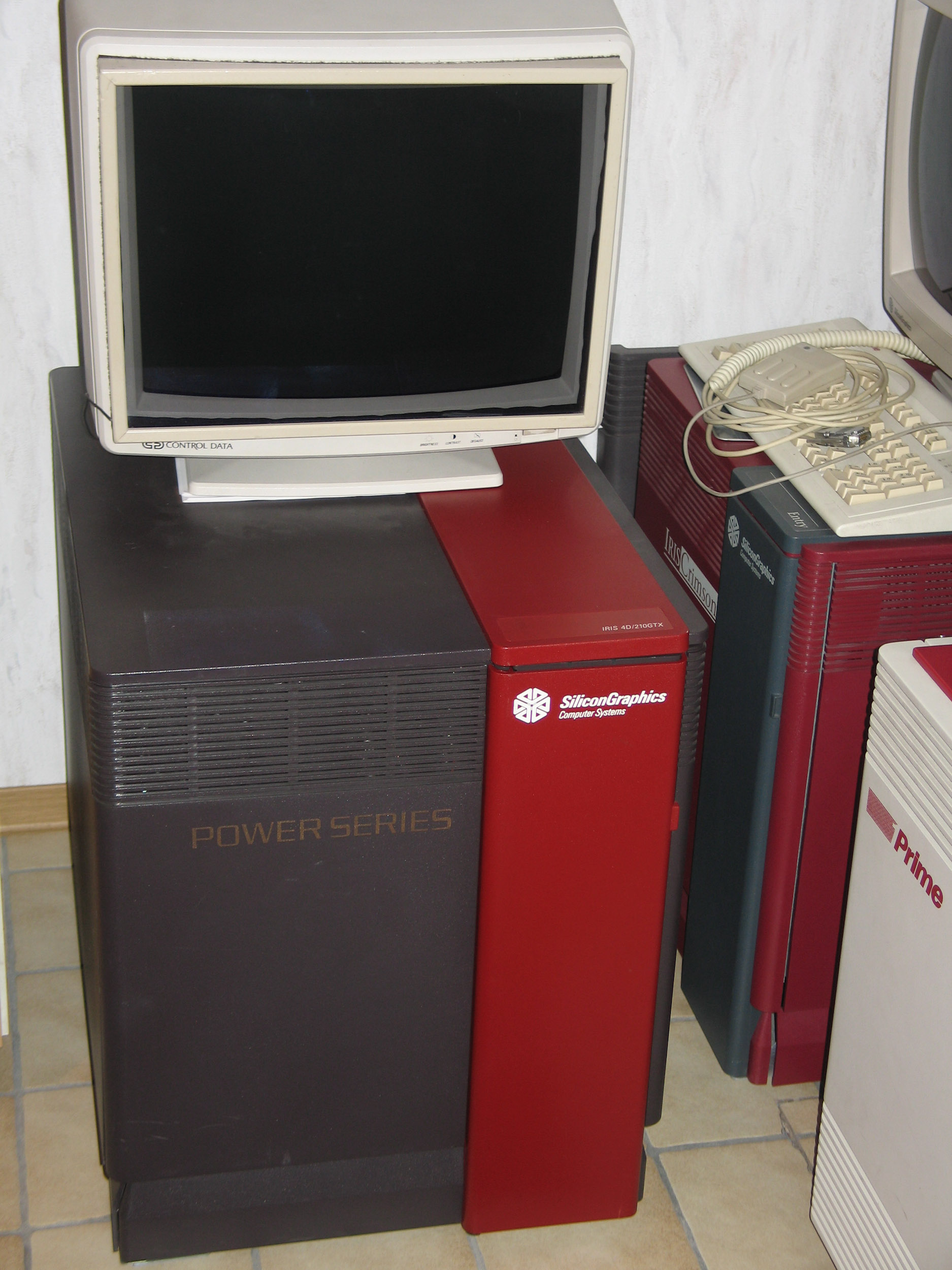
Diehard Single Tower
Description
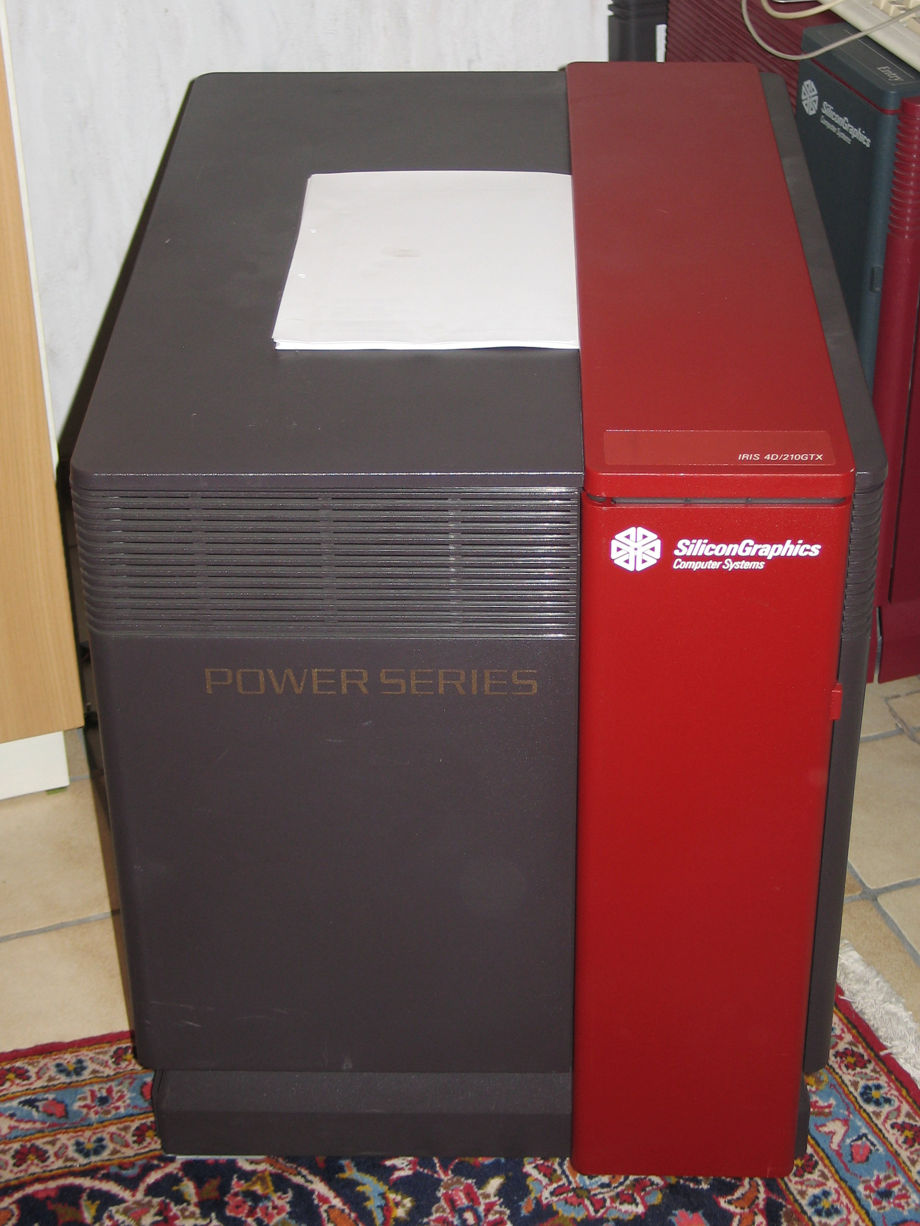
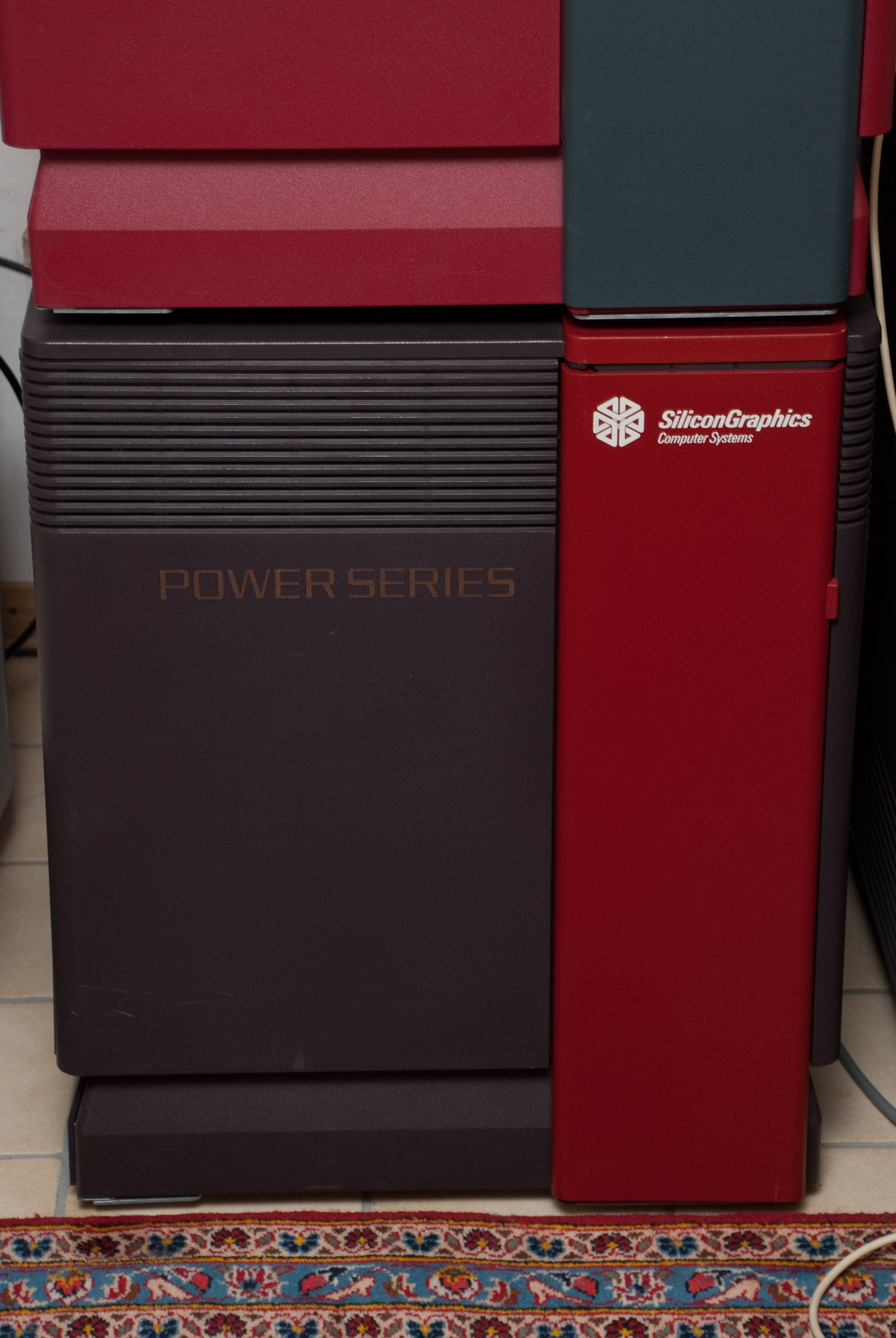
PowerSeries 4D/420VGX in PowerSeries 4D/240GTX skins.
The PowerSeries Single Tower (Diehard) has as the name says all parts of the system in one big enclosure. When viewed on the front the cardcage is behind a big door on the left of the machine, the drivebays and the system controller are on the right. It was used for all PowerSeries systems with up to 2 CPU boards with the exception of the 4D/120: 4D/210, 4D/220, 4D/240, 4D/310, 4D/320, 4D/340, 4D/420 and 4D/440.
width:     54 cm / 21"
height:    66 cm / 26"
depth:     74 cm / 29"

weight:    82 kg / 180 lbs
All systems have the word "PowerSeries" printed on the front. Again the systems are in dark brown/gray color and the type of graphics option was shipped with is indicated by the colored parts (small door on the right and the hat on top of the machine) and a small label on the top of it. GTX(B) machines have red, VGX(T) systems blue and server systems beige top hats and doors.
For information on cooling and power issues regarding a Crimson/Reality Engine upgrade (which was done in the field back then) see Crimson page.
Backplane Layout
| 1 | VME | The VME Slots have to be filled from left (#1) to right (#4) with no empty slots in-between. |
| 2 | VME | |
| 3 | VME | |
| 4 | VME | |
| 5 | IO | IO Controller |
| 6 | CPU | The slots for CPU boards must be filled from left (#6) to right (#7), so in systems with a single CPU board (single or dual CPU systems) slot #7 remains empty. |
| 7 | CPU | |
| 8 | MEM | The 14slot backplane has only 1 slot for a memory board because with high density SIMMs 256MB (the maximum) could be reached with one board. |
| 9 | GFX | How the graphics slots are used depends on the type of graphics option. See Graphics section. |
| 10 | GFX | |
| 11 | GFX | |
| 12 | GFX | |
| 13 | GFX | |
| 14 | GFX |
Status LED
The Single Tower has a yellow fault LED located newar the power switch. When the system is switched on both the fault LED and the green power LED are on. The yellow LED will no longer be lit if the system has passwd POST. A 1 digit LED status display is hidden behind the frontpanel.
Predator Rack
Description
The PowerSeries rackmount systems come in a dark refrigerator sized rack enclosure, that has space for a 19slot cardcage at the top and a lot of drives at the bottom. All this is hidden behind a huge front door that also has a small display, that shows CPU usage when the system is running.
width:     tba
height:    tba
depth:     tba

weight:    tba
There are three different configurations of the PowerSeries racks which have a different backplane and different labels. But still all are the same color and there is no color code for the graphics option that is installed. Instead there is a small label on the front door that names the original configuration of the system (for example "4D/480S"). Aside from that the server versions were labelled "POWERCENTER", the graphics supercomputers "PowerSeries" and the Skywriter of course "SKYWRITER".
Backplane Layout (PowerCenter)
| 1 | VME | The VME Slots have to be filled from left (#1) to right (#6) with no empty slots in-between. |
| 2 | VME | |
| 3 | VME | |
| 4 | VME | |
| 5 | VME | |
| 6 | VME | |
| 7 | IO | IO Controller |
| 8 | CPU | The slots for CPU boards must be filled from left (#8) to right (#11). |
| 9 | CPU | |
| 10 | CPU | |
| 11 | CPU | |
| 12 | MEM | The backplane has two memory slots which also should be populated from left (#12) to right (#13) |
| 13 | MEM | |
| 14 | IO | IO Controller |
| 15 | VME | The VME Slots have to be filled from left (#15) to right (#19) with no empty slots in-between. |
| 16 | VME | |
| 17 | VME | |
| 18 | VME | |
| 19 | VME |
Backplane Layout (PowerVision)
| 1 | VME | The VME Slots have to be filled from left (#1) to right (#6) with no empty slots in-between. |
| 2 | VME | |
| 3 | VME | |
| 4 | VME | |
| 5 | VME | |
| 6 | VME | |
| 7 | IO | IO Controller |
| 8 | CPU | The slots for CPU boards must be filled from left (#8) to right (#11). |
| 9 | CPU | |
| 10 | CPU | |
| 11 | CPU | |
| 12 | MEM | The backplane has two memory slots which also should be populated from left (#12) to right (#13) |
| 13 | MEM | |
| 14 | GFX | How the graphics slots are used depends on the type of graphics option. See Graphics section. |
| 15 | GFX | |
| 16 | GFX | |
| 17 | GFX | |
| 18 | GFX | |
| 19 | GFX |
Backplane Layout (Skywriter)
| 1 | VME | The VME Slots have to be filled from left (#1) to right (#4) with no empty slots in-between. |
| 2 | VME | |
| 3 | VME | |
| 4 | VME | |
| 5 | GFX | How the graphics slots are used depends on the type of graphics option. See Graphics section. |
| 6 | GFX | |
| 7 | GFX | |
| 8 | GFX | |
| 9 | GFX | |
| 10 | GFX | |
| 11 | IO | IO Controller |
| 12 | CPU | The slots for CPU boards must be filled from left (#12) to right (#13). |
| 13 | CPU | |
| 14 | MEM | The Skywriter backplane has only 1 slot for a memory board because with high density SIMMs 256MB (the maximum) could be reached with one board. |
| 15 | GFX | How the graphics slots are used depends on the type of graphics option. See Graphics section. |
| 16 | GFX | |
| 17 | GFX | |
| 18 | GFX | |
| 19 | GFX | |
| 20 | GFX |
Specials
Rebadged Systems
Relabeld PowerSeries systems were available from several companies, the most common being
- Control Data
- Siemens Nixdorf RW360
Skywriter
A Skywriter is a rackmount PowerSeries system that has a special backplane which allows to install two graphics options in one machine. This special feature came with a price, which was that the backplane had only 2 instead of 4 slots for CPU boards, so original Skywriter systems are 4D/340 or 4D/440 PowerSeries computers. The original graphics option that came with Skywriters was VGXT, but there is also mention of dual Reality Engine configurations. The interersting thing about the Skywriter was, that the two graphics option could either drive different displays or work together on the same output ("Cyclops mode").
Problems
Operating System
Choosing an operating system.
The Power Series systems were introduced when 4D1-3.x was available. Later models and newer graphics options are not supported by 4D1-3.x releases.
The all platform versions of 4D1-4.x include support for all basic Power Series models with the exception of the Reality Engine graphics which was introduced towards the end of the Power Series production. In software it was first supported with 4D1-4.0.5 or subversions thereof.
General support for the Power Series systems can be found in the all platform releases of IRIX 5.x. Support for the Power Series has ended with the release of the final version IRIX 5.3.
Mode Switches
What the hell are the DIP switches labeled "Mode"?
The DIP switches are found close to the main power switch at the front of the Twin Tower systems. Their function isn't covered in public documentation, but an old Usenet post lists at least some of the possible settings:
switch #s   hex   meaning
87654321    --    --
00000000    00    Default (all switches are closed)
10000001    81    PON Mode (drops into pon>)
10000010    82    SYMMON (unknown)
10000100    84    NODIAG (bypasses running power-on tests)
10001000    88    MPDEBUG (unknown)
These switches are also present on Single Tower systems. They are on a PCA behind the frontpanel which holds the power/reset button as well as the status LEDs.
SCSI configuration (Single Tower)
The possibilities to configure the 2 SCSI channels of an IO3/IO3B in the Diehard chassis.
At first it is important to understand where the SCSI cables come from and where they go to. The following short description tracks the cables beginning from the connectors below the drivebeays.
The top connector goes to the top drivebays and backplane SCSI connection, the bottom connector goes to the bottom drivebays and cardcage SCSI connection.
- Jumpered configuration: Both bottom connectors are bridged using a short SCSI cable, the internal connector dangling from the cardcage top is NOT connected to the IO board. In this case all internal drives are on one SCSI chain (#0, the one routed via backplane). The external SCSI chain (#1) can be used with externall connectors installed on the IO panel.
- Non-Jumpered (i.e. terminated) configuration: Both connectors at the bottom are terminated, the internal connector is attached to the IO board. In this case both SCSI channels (#0, #1) can be used internally (lower bays: #0, upper bays: #1). Instead of termination external SCSI devices may be attached to either chain using the connectors at the bottom of the machine.
The following table shows the number of devices that can be attached to the two SCSI channels in the 2 basic configurations:
Jumpered
   Channel #0:      internal 4 / external 0
   Channel #1:      internal 0 / external 7
Non-Jumpered (i.e. Terminated)
   Channel #0:      internal 2 / external 5
   Channel #1:      internal 2 / external 5
Pictures
PowerSeries Single Tower
PowerSeries 4D/420VGX in PowerSeries 4D/240GTX skins.
PowerSeries 4D/420VGX in PowerSeries 4D/240GTX skins.
PowerSeries 4D/420VGX in PowerSeries 4D/240GTX skins.

PowerSeries 4D/420VGX in PowerSeries 4D/240GTX skins.
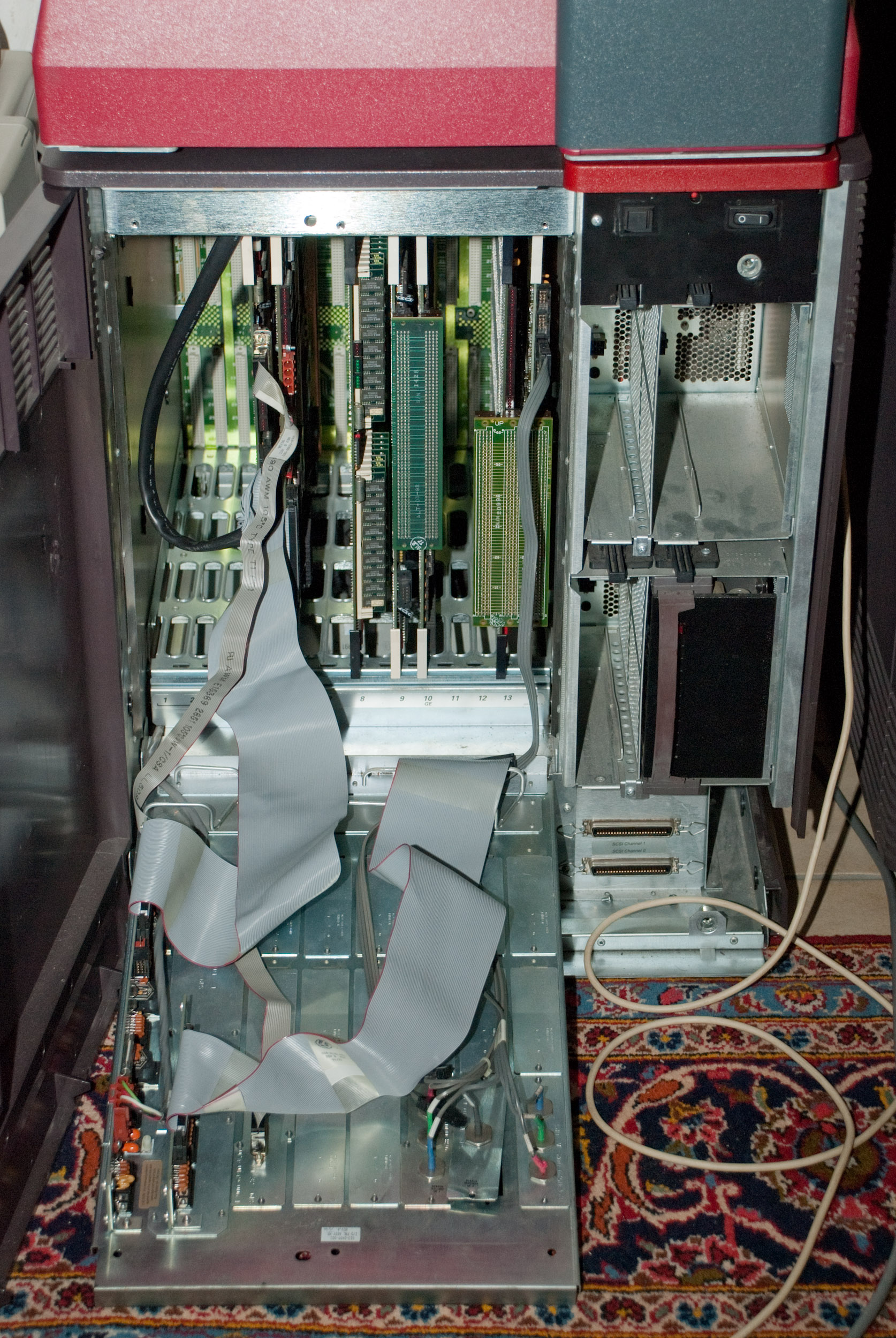
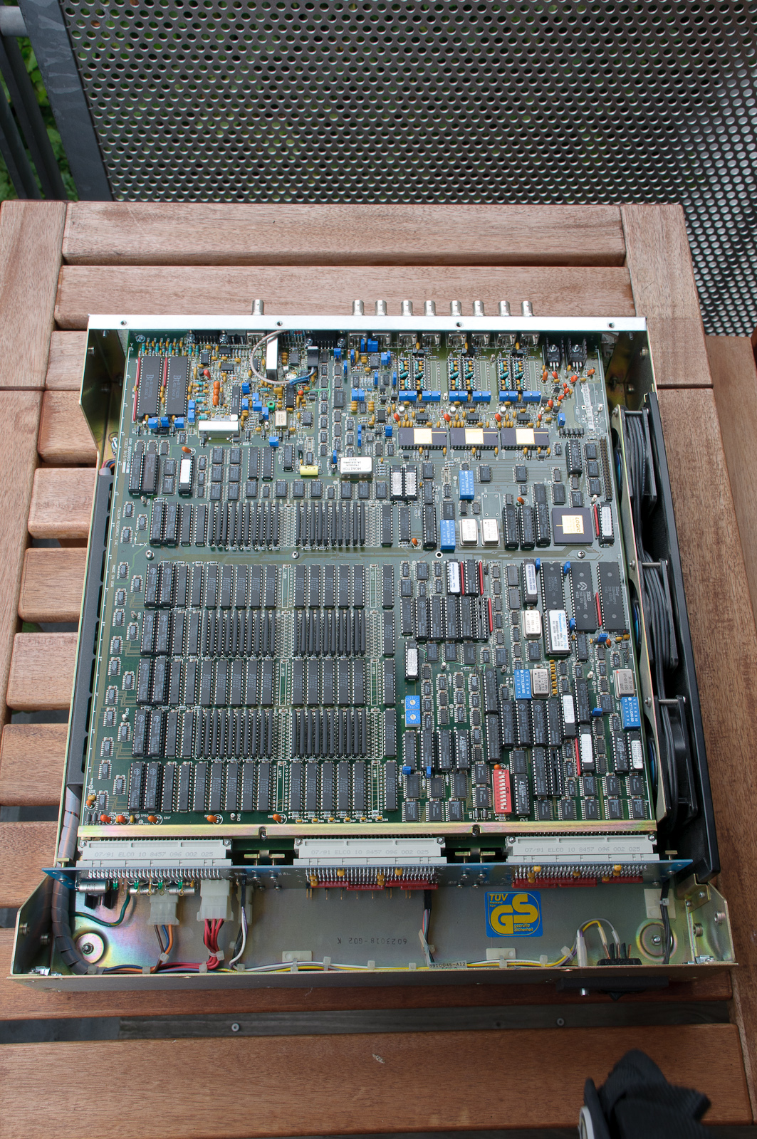
Cardcage view of a 4D/420 VGX.
CPU
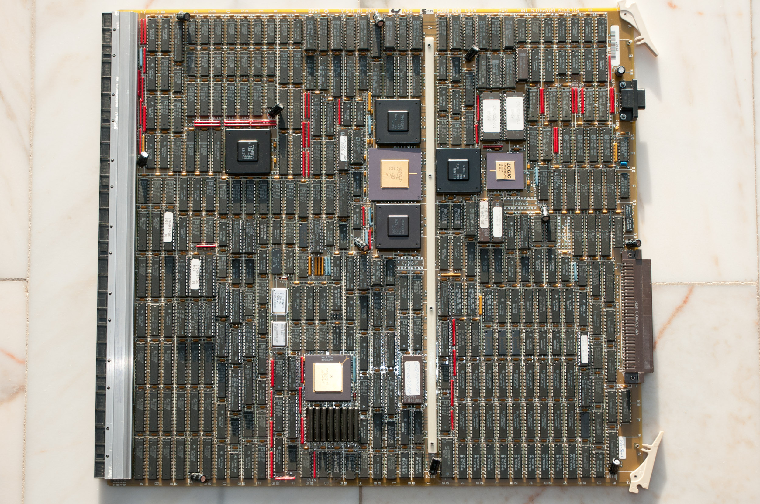
IP7 CPU board, 2 MIPS R3000.
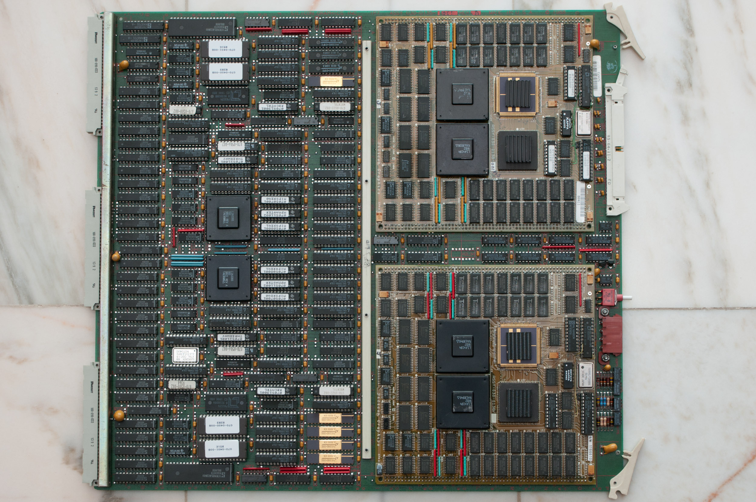
IP7 CPU (2x R3000)
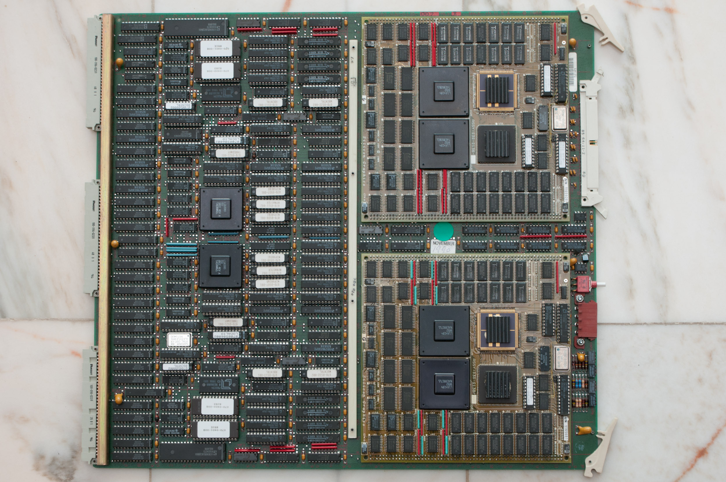
IP7 CPU (2x R3000)
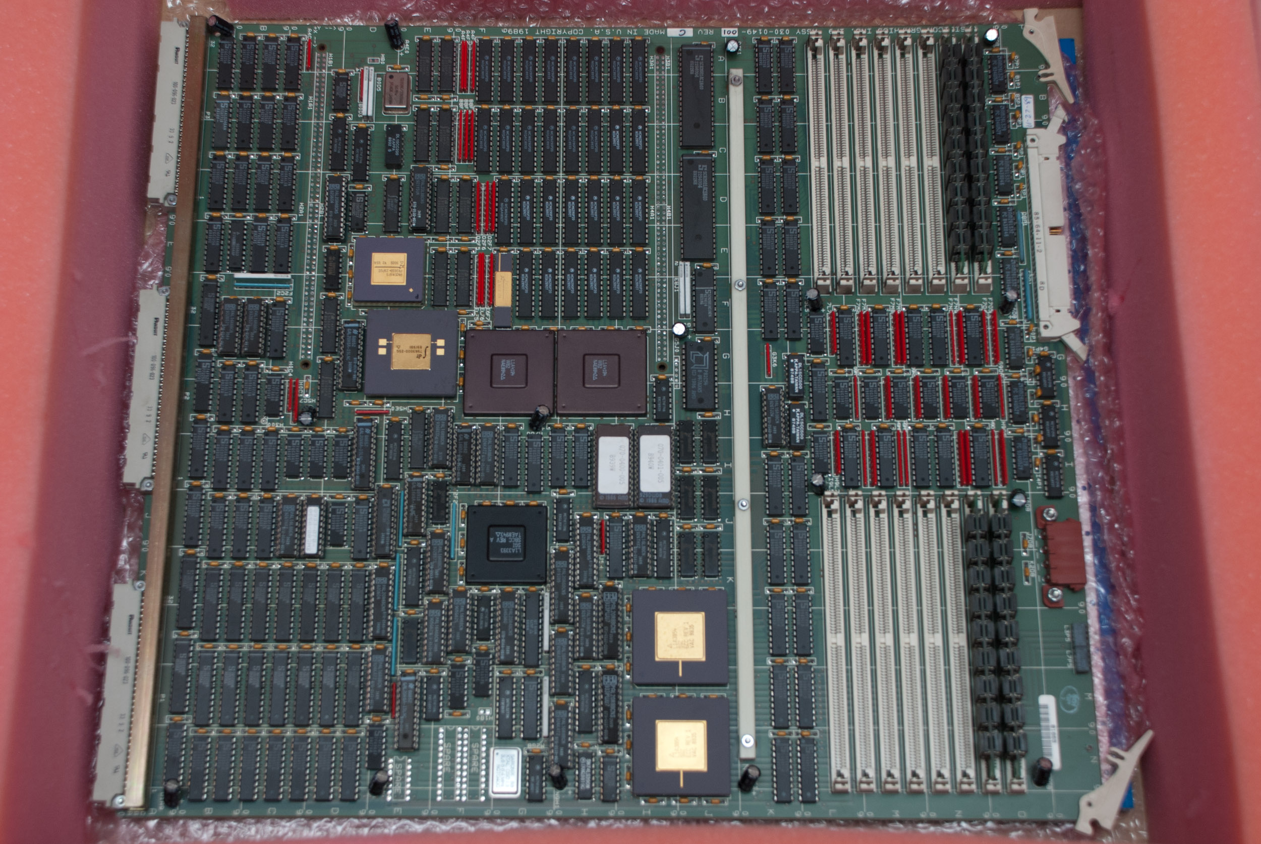
IP9 CPU board, 1 MIPS R3000 with memory.
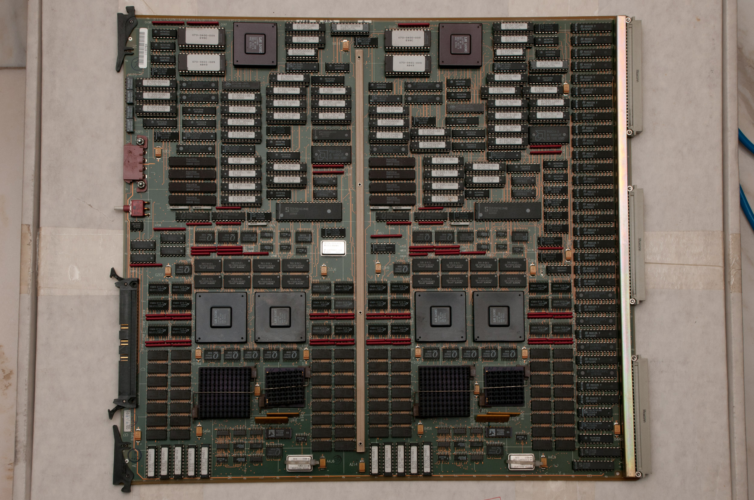
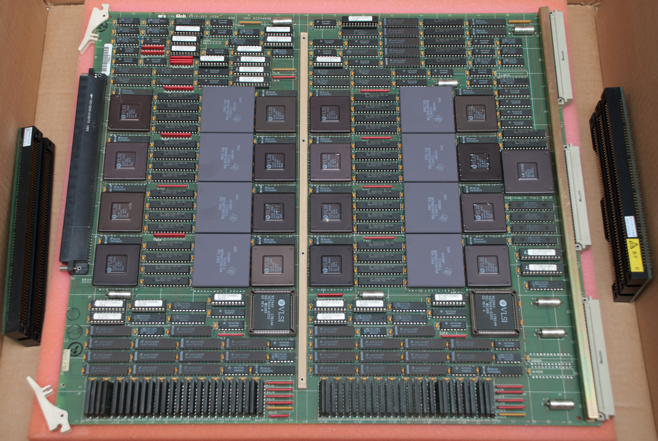
IP15 CPU board, 2 MIPS R3000.
IO
IO2 board.
PowerSeries IO2 board.
IO3 board.
Memory
MC2 memory board fully populated.

MC2 memory board early version
MC2 memory board.
MC2 memory board.
MC2 memory board.

MC2 memory for PowerSeries system.
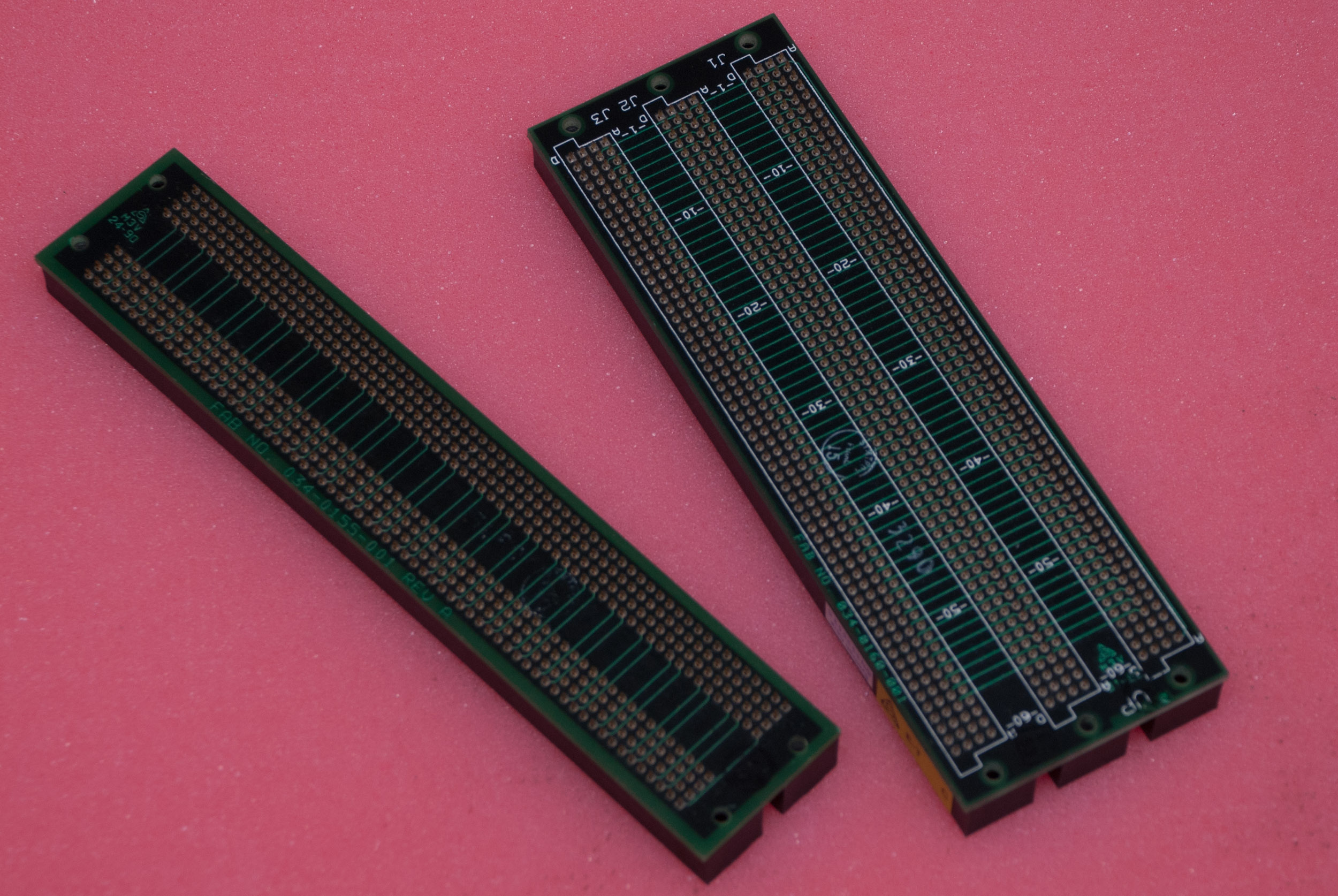
Backplane
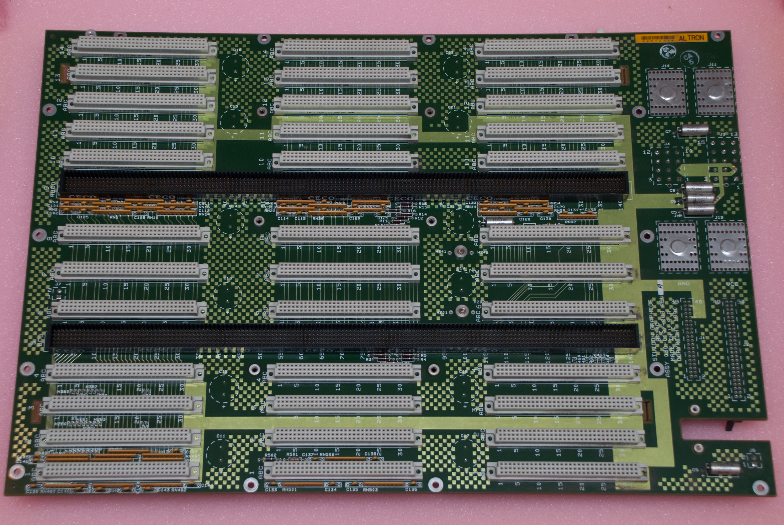
14-slot Single Tower backplane, connector side.
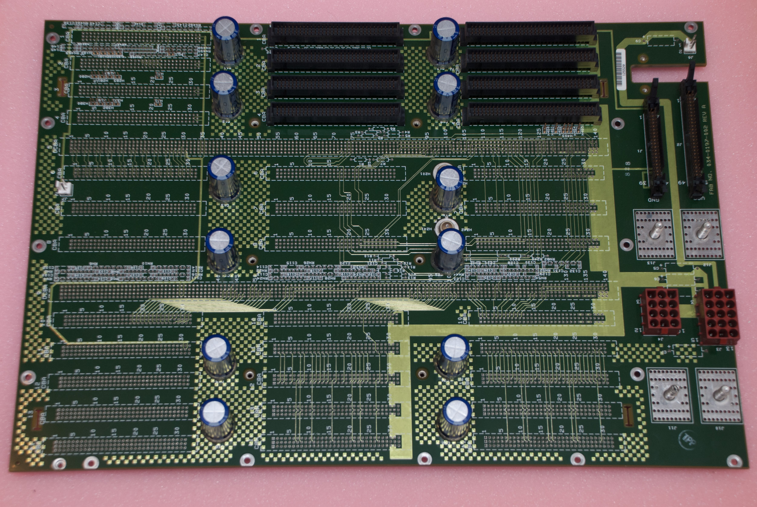
14-slot Single Tower backplane, back side.
VME Options
CNC Ethernet
ESDI controller
Elan Graphics
Elan Graphics for Crimson and PowerSeries.
GTX Graphics
GTX GM2 Graphics Manager.
GTX GE4 Geometry Engine.

GTX RM1 Raster Manager.
GTX RM1 Raster Manager.

GTX RV1.5 Raster Video.
GTX connector.
VGX Graphics

VGX Graphics Manager (GM3).
VGX Geometry Engine (GE6).
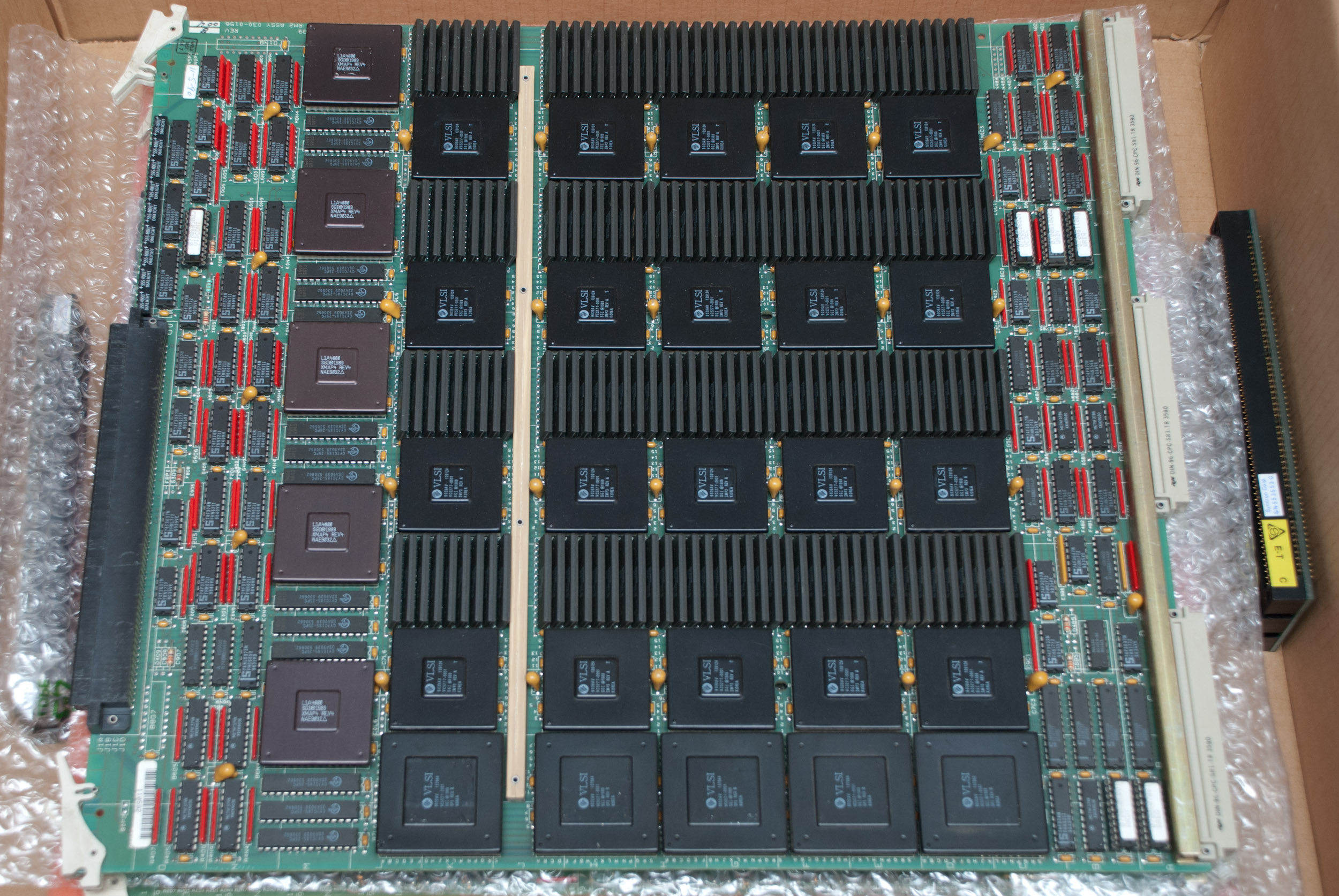
VGX Raster Manager (RM2).

VGX Display Generator (DG1)
VGX card edge connector.
SCSI Video Creator
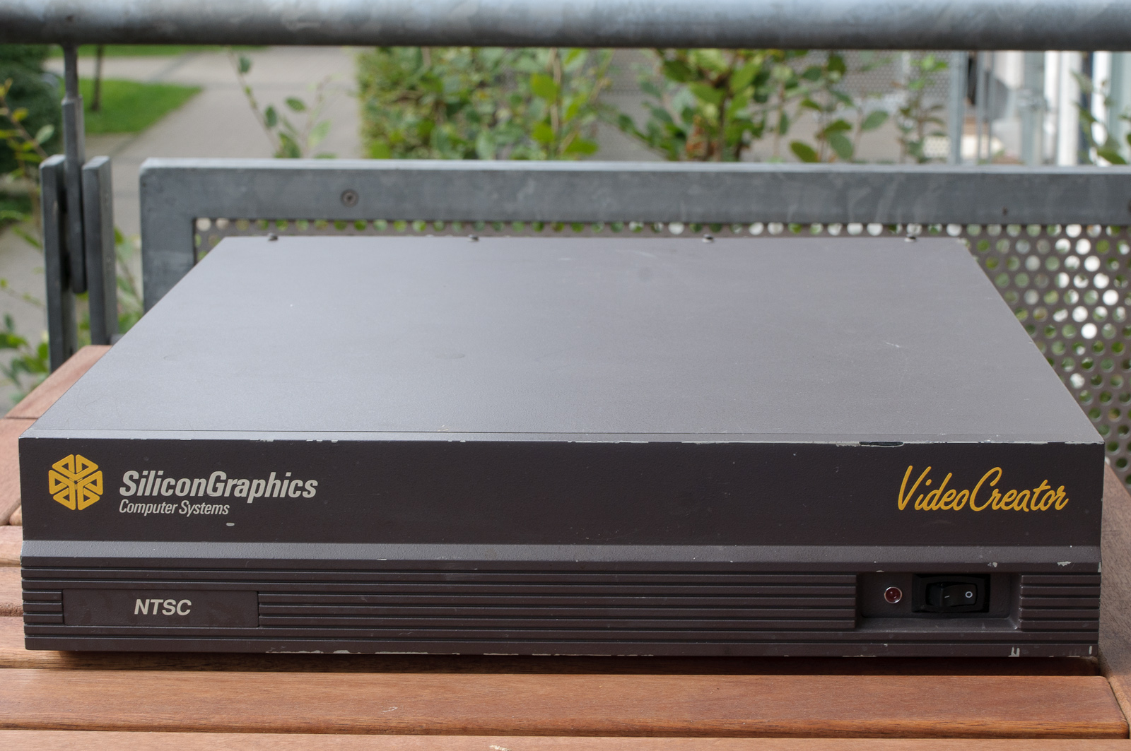
Video Creator external version.
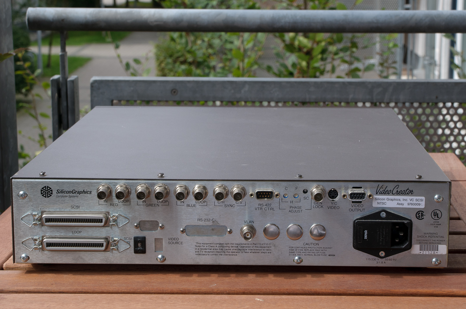
Connector panel of external Video Creator.
Interior view, showing the VME board.
Links
SGI Press Releases
- 1988, October - Silicon Graphics Announces New Multiprocessing IRIS PowerSeries [local]
Articles
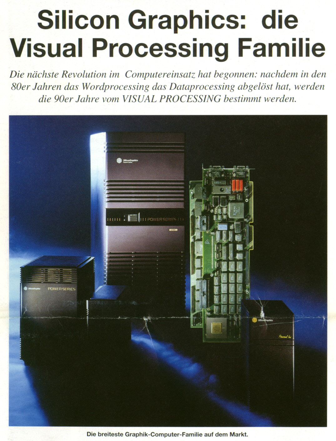
- Silicon Graphics: die Visual Processing Familie (Scan by Ganjatron)
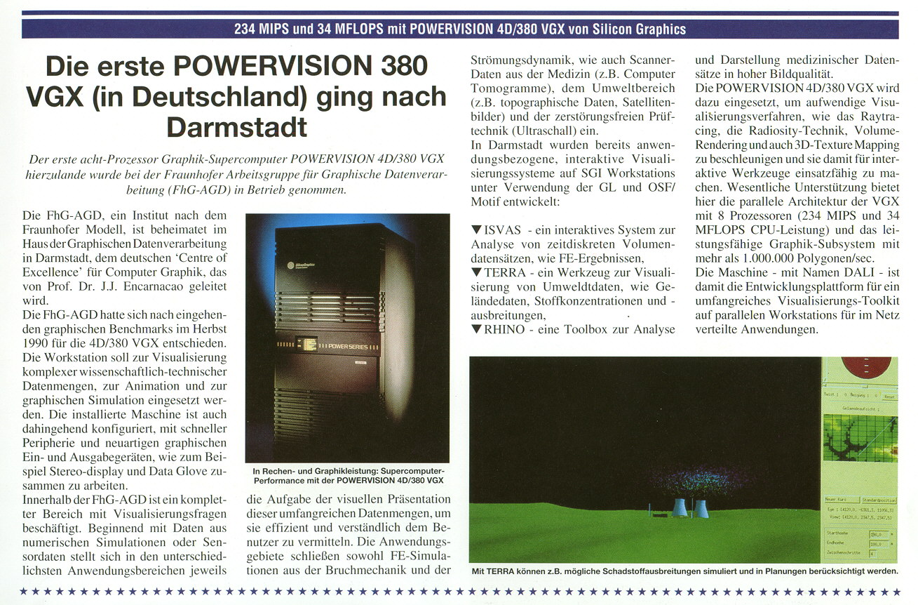
- Die erste POWERVISION 380 VGX (in Deutschland) ging nach Darmstadt (Scan by Ganjatron)
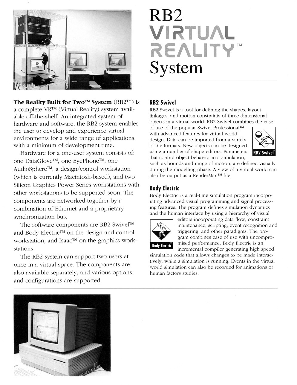
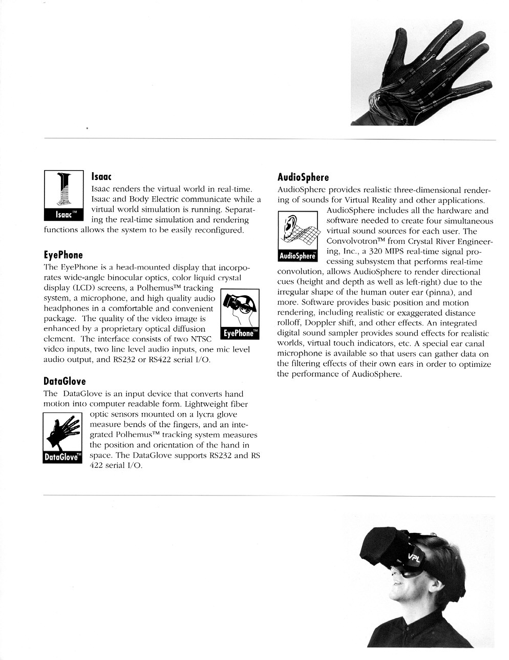
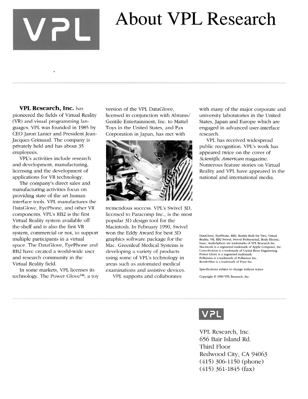
- VPL Research paper (featuring a Powerseries TwinTower): Page 1, 2, 3, 4 (Scan by Ganjatron)
Websites
- This Old SGI - lots of information on the old 4D series systems of all sizes [local mirror]
- Big Old Nasty SGI Page - lots of pictures, good information on the old and big systems
- Crimson/PowerSeries/Onyx RealityEngine/RealityEngine2 Info [local mirror]