Graphics
PowerVision
Introduction
General
The PowerVision graphics subsystem is the "second generation" of graphics options available for the Silicon Graphics PowerSeries (and Crimson) machines and is the first to feature hardware texture support. VGX was introduced around 1990, VGXT a bit later. VGXT has "better" texture support (higher fill rate, perspective textures) - the "T" or the lack thereof does not mean that VGXT supports textures in hardware and VGX not.
One of the most interesting systems of this era is the Silicon Graphics Skywriter which is a multiprocessor PowerSeries system in a Rackmount enclosure with two VGX(T) graphics subsystems capable of driving two completely independent displays. So Skywriter is not the name of a graphics option or a basic machine, it is a name of a specialized configuration.
Features
PowerVision Graphics (VGX and VGXT) includes:
24-bit color, double buffered
8-bit alpha (transparency), double buffered
24-bit Z-buffer
8 stencil bitplanes
4 Overlay (8 planes, double buffered [optional]) and 8 Window planes
1280 x 1024 standard screen resolution
Programmable video timing up to HDTV (1920 x 1024 @ 30Hz Interlaced)
Support for live video input and output options
Optional genlock capability
Stereoscopic viewing support/Stereo-ready monitor

Advanced graphics features include hardware support for:
Subpixel positioning
Advanced lighting models:
Multiple colored light sources (up to 8)
Ambient, diffuse, and specular lighting models
Phong lighting
Real-Time Texture Mapping
Real-Time Anti-aliasing of all Primitives (polycons, lines, points)
Spotlights (Local and infinite light source positioning; Two-sided lighting)
High-speed graphics DMA with pan and zoom capabilities
Atmospheric effects
Sphere rendering
Pixel-blending capabilities for transparency effects
Full scene anti-allasing
Soft shadows and depth-of-field
FFTs and convolutions
Multimode windowing environment
VGX vs. VGXT
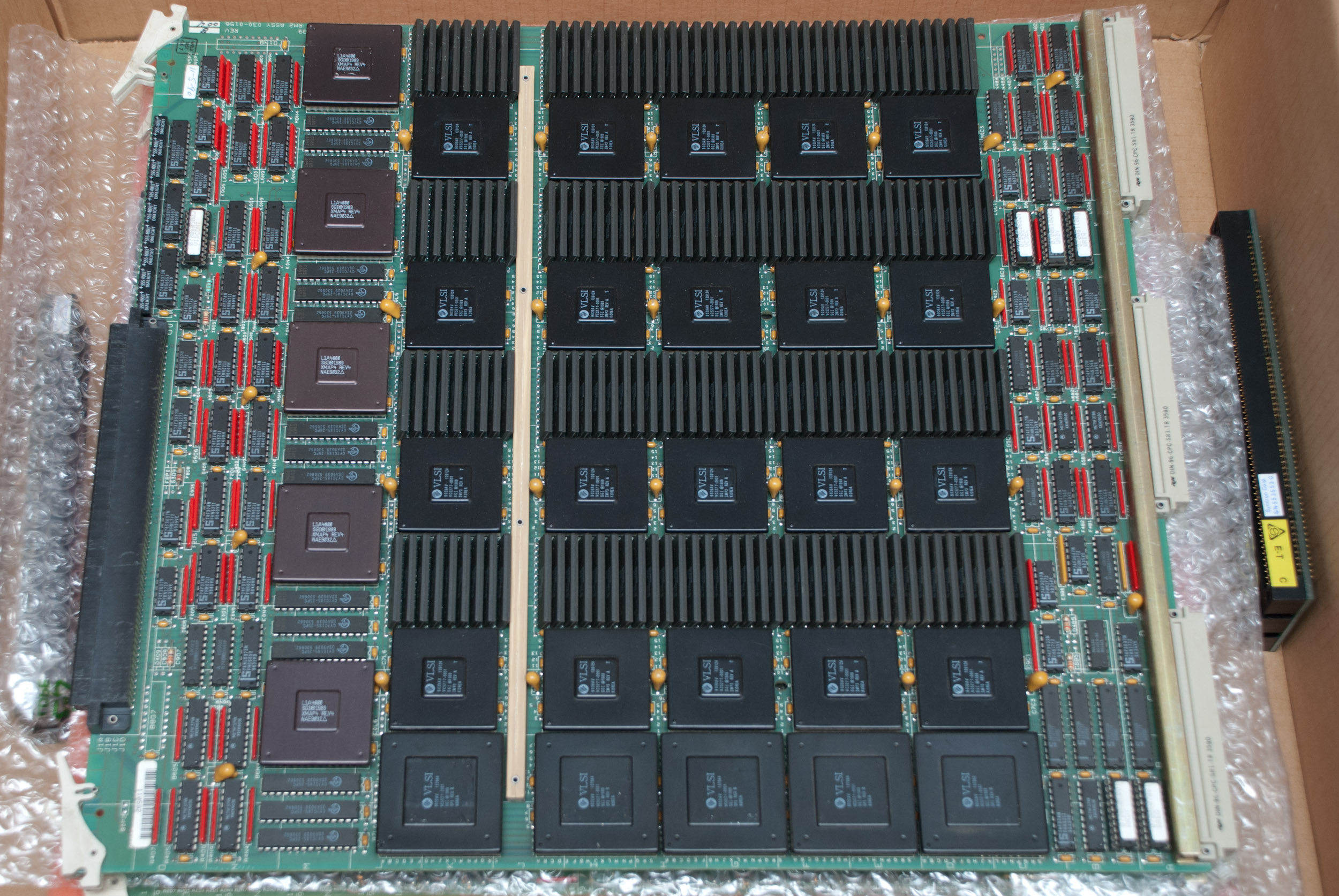
As previously stated the obvious difference is that VGX uses a RM2 and the VGXT a RM3 Raster Manager board. Although they both support textures (so that is not what the "T" stands for!) there are significant differences. The RM2 uses IMP3 image engines, while the RM3 uses IMP5. This leads to the following basic differences/improvements:
- higher pixel fill rate - for bilinear mipmapped textures 50M pixels/sec (VGXT) instead of 17M pixels/sec (VGX)
- per pixel fog and haze computations added on VGXT
- per pixel perspective correction for textures added on VGXT
- more efficient texture memory usage on VGXT - textures can span memory bank boundaries on VGXT, while VGX does not allow that
Boards
VGX
- GE6
- Geometry Engine Board
- GM3
- Graphics Manager Board
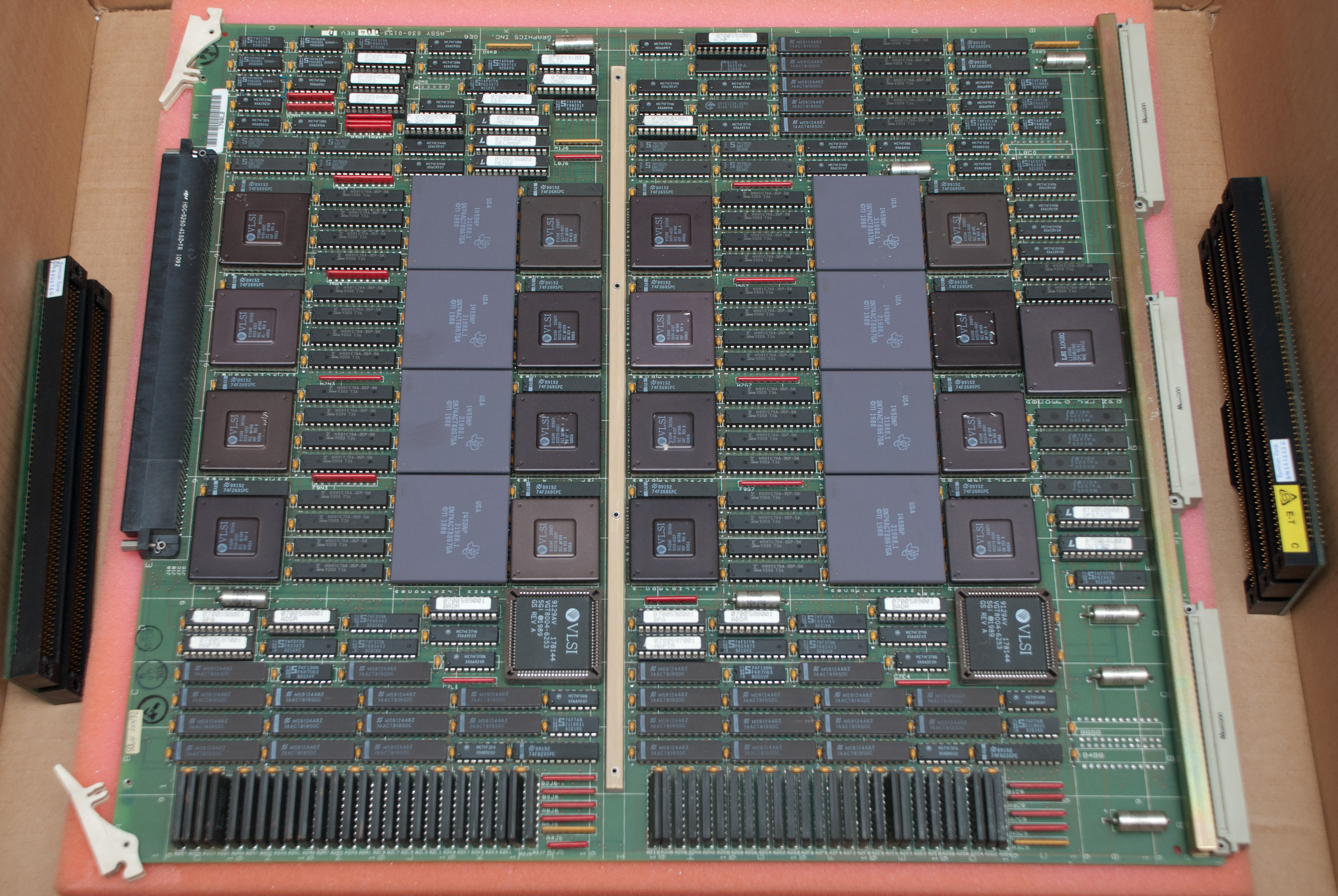
- RM2
- Raster Manager Board which uses 20 IMP3 IMage Processing engines. A VGX setup can contain one (5-span VGX) or two (10-span VGX) Raster Manager Boards.
- DG1
- Display Generator Board
The DG1 board has 5 connectors on the card edge. Their function is as follows (top to bottom):
- GENLOCK sync output
- Alpha output
- RGB video out and sync to monitor (BNC)
- Super VHS and composite video (used if you have EV1 video option)
- GENLOCK RGB input
VGXT
- GE6
- Geometry Engine Board
- GM3 or GM3B
- Graphics Manager Board
- RM2
- Raster Manager Board which uses 20 IMP5 IMage Processing engines. A VGXT setup can contain one (5-span VGXT) or two (10-span VGXT) Raster Manager Boards.
- DG1
- Display Generator Board
The DG1 board has 5 connectors on the card edge. Their function is as follows (top to bottom):
- GENLOCK sync output
- Alpha output
- RGB video out and sync to monitor (BNC)
- Super VHS and composite video (used if you have EV1 video option)
- GENLOCK RGB input
Skywriter
A Skywriter uses two complete VGXT boardsets accompanied by the VX1 board that allows it to generate 2 seperate displays or one display with both VGXT boardsets working on it ("cyclops mode").
Setup
VGX
The following shows the configuration for a 15 slot TwinTower (PowerSeries) system:
| 10 | GFX | GM3 | Slots 10 and 11 are bridged using a card edge connector. |
| 11 | GFX | GE6 | |
| 12 | GFX | ||
| 13 | GFX | RM2 (optional) | Slots 13 to 15 are bridged using a card edge connector. Some video options are used in the slot marked as empty and do come with a special edge connector that spans this slot as well. |
| 14 | GFX | RM2 | |
| 15 | GFX | DG1 |
The following shows the configuration for a SingleTower (PowerSeries) system:
| 9 | GFX | GM3 | Slots 9 and 10 are bridged using a card edge connector. |
| 10 | GFX | GE6 | |
| 11 | GFX | ||
| 12 | GFX | RM2 (optional) | Slots 12 to 14 are bridged using a card edge connector. Some video options are used in the slot marked as empty and do come with a special edge connector that spans this slot as well. |
| 13 | GFX | RM2 | |
| 14 | GFX | DG1 |
The following shows the configuration for a Rack (PowerSeries) system:
| 14 | GFX | GM3 | Slots 14 and 15 are bridged using a card edge connector. |
| 15 | GFX | GE6 | |
| 16 | GFX | ||
| 17 | GFX | RM2 (optional) | Slots 17 to 19 are bridged using a card edge connector. Some video options are used in the slot marked as empty and do come with a special edge connector that spans this slot as well. |
| 18 | GFX | RM2 | |
| 19 | GFX | DG1 |
VGXT
The following shows the configuration for a 15 slot TwinTower (PowerSeries) system:
| 10 | GFX | GM3 | Slots 10 and 11 are bridged using a card edge connector. |
| 11 | GFX | GE6 | |
| 12 | GFX | ||
| 13 | GFX | RM3 (optional) | Slots 13 to 15 are bridged using a card edge connector. Some video options are used in the slot marked as empty and do come with a special edge connector that spans this slot as well. |
| 14 | GFX | RM3 | |
| 15 | GFX | DG1 |
The following shows the configuration for a SingleTower (PowerSeries) system:
| 9 | GFX | GM3 | Slots 9 and 10 are bridged using a card edge connector. |
| 10 | GFX | GE6 | |
| 11 | GFX | ||
| 12 | GFX | RM3 (optional) | Slots 12 to 14 are bridged using a card edge connector. Some video options are used in the slot marked as empty and do come with a special edge connector that spans this slot as well. |
| 13 | GFX | RM3 | |
| 14 | GFX | DG1 |
The following shows the configuration for a Rack (PowerSeries) system:
| 14 | GFX | GM3 | Slots 14 and 15 are bridged using a card edge connector. |
| 15 | GFX | GE6 | |
| 16 | GFX | ||
| 17 | GFX | RM3 (optional) | Slots 17 to 19 are bridged using a card edge connector. Some video options are used in the slot marked as empty and do come with a special edge connector that spans this slot as well. |
| 18 | GFX | RM3 | |
| 19 | GFX | DG1 |
The following shows the configuration for a Skywriter (PowerSeries) system:
| 5 | GFX | DG1 | Slots 17 to 19 are bridged using a card edge connector. Some video options are used in the slot marked as empty and do come with a special edge connector that spans this slot as well. It is unclear if a Skywriter setup would allow such video option in none, one or both of the VGXT graphics options. |
| 6 | GFX | RM3 | |
| 7 | GFX | RM3 | |
| 8 | GFX | ||
| 9 | GFX | GE6 | Slots 9 and 10 are bridged using a card edge connector. |
| 10 | GFX | GM3 | |
| ... | |||
| 14 | GFX | GM3 | Slots 14 and 15 are bridged using a card edge connector. |
| 15 | GFX | GE6 | |
| 16 | GFX | ||
| 17 | GFX | RM3 (optional) | Slots 17 to 19 are bridged using a card edge connector. Some video options are used in the slot marked as empty and do come with a special edge connector that spans this slot as well. It is unclear if a Skywriter setup would allow such video option in none, one or both of the VGXT graphics options. |
| 18 | GFX | RM3 | |
| 19 | GFX | DG1 |
Pictures

VGX Graphics Manager (GM3).
VGX Geometry Engine (GE6).
VGX Raster Manager (RM2).

VGX Display Generator (DG1)
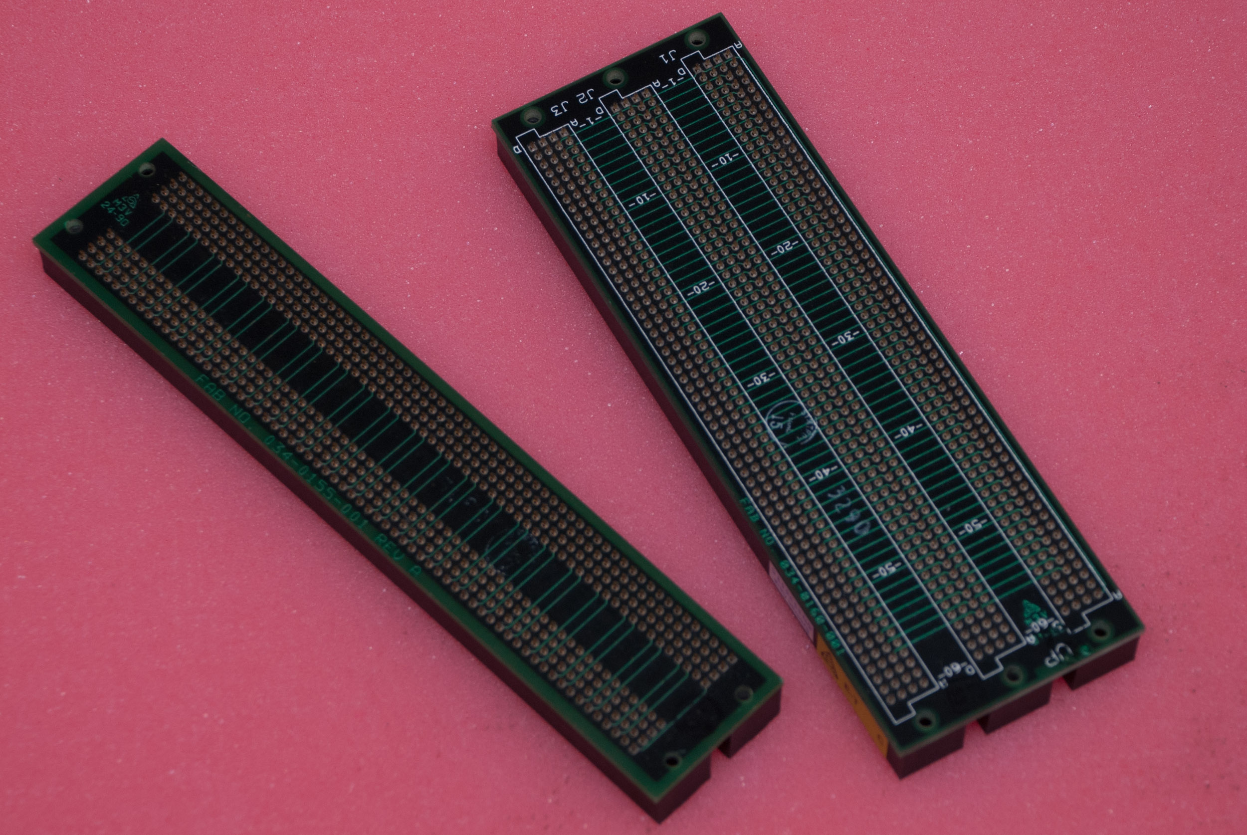
VGX card edge connector.